System diagnosis device and system diagnosis method

A diagnostic device and diagnostic method technology, applied in general control systems, control/adjustment systems, test/monitoring control systems, etc., can solve problems such as high cost, complicated design, and inconvenient real-time and intuitive understanding of faults by users

Active Publication Date: 2019-03-29
LENOVO (BEIJING) LTD
View PDF9 Cites 0 Cited by
  • Summary
  • Abstract
  • Description
  • Claims
  • Application Information

AI Technical Summary

Problems solved by technology

Such a system diagnostic device usually requires high cost and complex design due to the need for dedicated hardware design.
In addition, because the diagnostic logs about hardware failures are stored inside the motherboard controller, it is not convenient for users to understand the specific conditions of the failures in real time and intuitively.

Method used


Image

  • System diagnosis device and system diagnosis method
  • System diagnosis device and system diagnosis method
  • System diagnosis device and system diagnosis method

Examples


Embodiment Construction

[0021] In order to make the objects, technical solutions and advantages of the present invention more apparent, exemplary embodiments according to the present invention will be described in detail below with reference to the accompanying drawings. Apparently, the described embodiments are only some embodiments of the present invention, rather than all embodiments of the present invention, and it should be understood that the present invention is not limited by the exemplary embodiments described here. Based on the embodiments of the present invention described in this disclosure, all other embodiments obtained by those skilled in the art without creative effort shall fall within the protection scope of the present invention.

[0022] Hereinafter, preferred embodiments of the present invention will be described in detail with reference to the accompanying drawings.

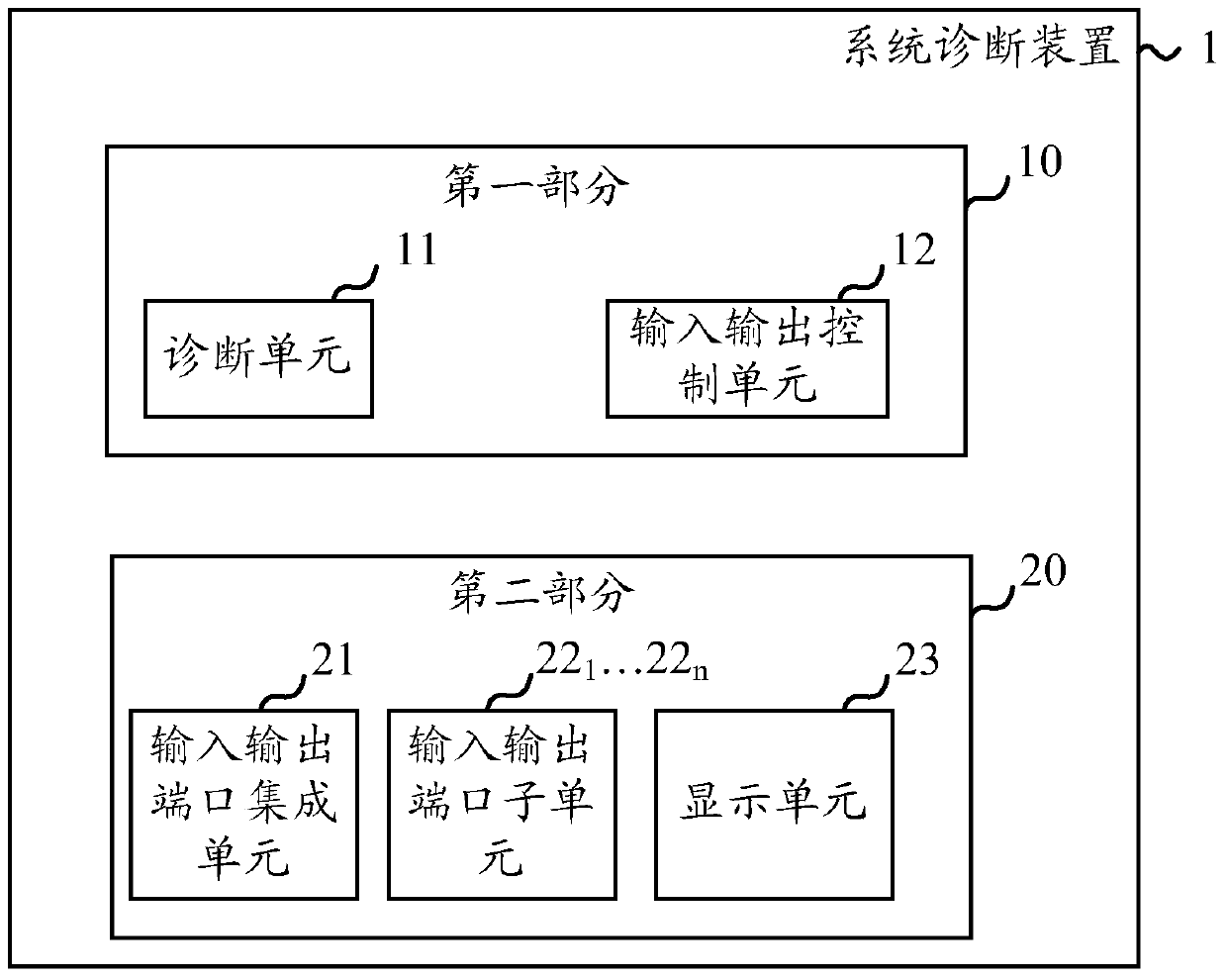
[0023] figure 1 is a functional block diagram illustrating a system diagnostic device according to an embodimen...


PUM


Abstract

The present invention discloses a system diagnostic device and a system diagnosis method. The system diagnostic device comprises a diagnosis unit used for generating the diagnosis data for indicating the fault information; an input output control unit used for sending the control data to the diagnosis unit; an input output port integrated unit used for receiving a diagnosis control signal from the diagnosis unit and receiving the input output data from the input output control unit, wherein the diagnosis unit and the control unit are arranged at a first part of the system diagnostic device, the input output port integrated unit is arranged at a second part of the system diagnostic device, and the first part and the second part are separated mutually.

Description

technical field [0001] The invention relates to the field of hardware diagnosis. More specifically, the present invention relates to a system diagnosis device and a system diagnosis method thereof. Background technique [0002] At present, in hardware systems used in servers, etc., a dedicated processing unit such as a motherboard controller (BMC) is usually used to perform hardware fault diagnosis, and fault diagnosis during system startup and operation. Since such a system diagnostic device requires dedicated hardware design, the cost is generally high and the design is complicated. In addition, since the diagnostic logs about hardware failures are stored inside the motherboard controller, it is not convenient for users to understand the specific conditions of the failures in real time and intuitively. [0003] Therefore, it is desirable to provide a system diagnosis device and a system diagnosis method, which can utilize the existing components of the hardware system, r...

Claims


Application Information

Patent Timeline
Patent Type & Authority Patents(China)
IPC IPC(8): G05B23/02
CPCG05B23/0221G05B2219/24065
Inventor 李权胡斌彭文武
Owner LENOVO (BEIJING) LTD
Why Eureka
Try Eureka