

Multi-rotor unmanned aerial vehicle based on pulling force measurement and flight control method thereof
A multi-rotor UAV and tensile force measurement technology, applied in the field of UAV flight, can solve the problems of not being able to provide and not reaching the three expected torque values of the total tensile force, and achieve the effect of avoiding insufficient lift and shortening the attitude control process.
- Summary
- Abstract
- Description
- Claims
- Application Information
AI Technical Summary
Problems solved by technology
Method used
Image

Examples
Embodiment 1
[0036] This embodiment provides a multi-rotor UAV based on tension measurement, which includes a body, a plurality of arms, a motor, an elastic body base, and a rotor arranged on the motor;
[0037] The motors are in one-to-one correspondence with the rotors;
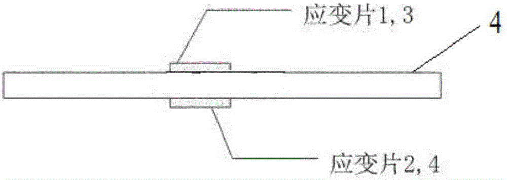
[0038] The elastic body base is arranged on the machine arm, the motor is arranged on the elastic body base, and a deformation measurement sensor is arranged on the elastic deformation zone of the elastic body base to detect the movement of the motor. pull.
[0039] If the traditional multi-rotor UAV does not use speed feedback, the actual lift of the UAV is affected by two factors: ① the actual speed of the motor does not reach the desired speed, ② the air flow generated by the front propeller when the UAV moves horizontally efficiency is reduced. If the traditional multi-rotor UAV adopts speed feedback, the actual lift of the UAV will be affected by a factor, that is, the efficiency reduction caused by the air flow ...
Embodiment 2
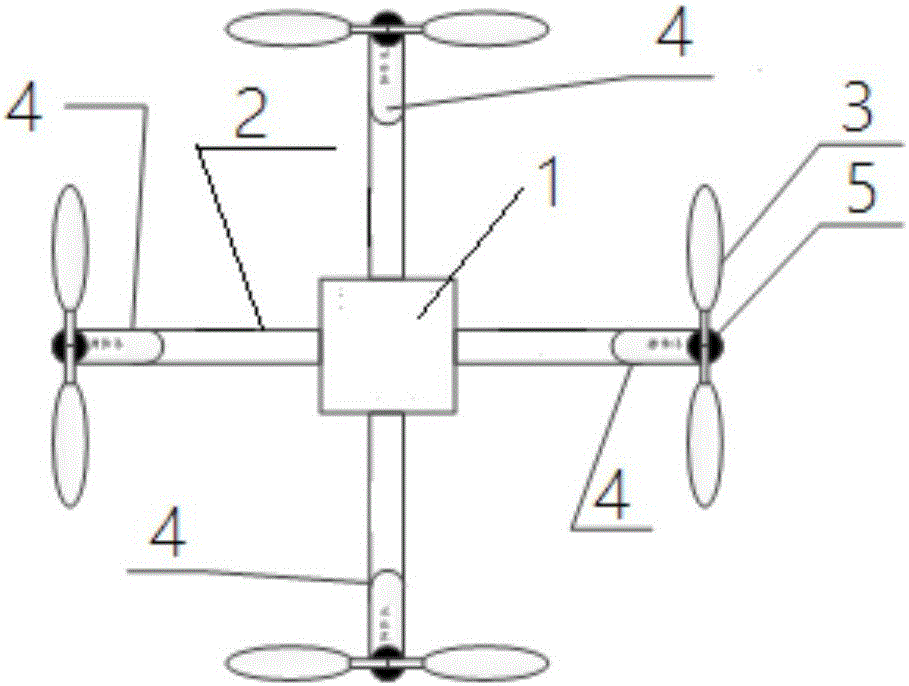
[0042] Such as figure 1 As shown, the multi-rotor UAV based on tension measurement provided in this embodiment includes a body 1, a plurality of arms 2, a motor 5, an elastomer base 4 and a rotor 3 arranged on the motor 5; The motor 5 is in one-to-one correspondence with the rotor 3; the elastomer base 4 is arranged on the arm 2, the motor 5 is arranged on the elastomer base 4, and the elastomer base 4 A deformation measurement sensor is arranged on the elastic deformation zone of the elastic deformation zone to detect the pulling force of the motor 5 .
[0043] Wherein the machine arm 2 can be multiple, and a plurality of machine arms 2 are evenly arranged around the body 1, preferably four or six, when there are four machine arms 2, the four machine arms 2 can be distributed in a cross or X shape Distribution, each arm 2 is provided with a rotor 3, or two rotors 3.
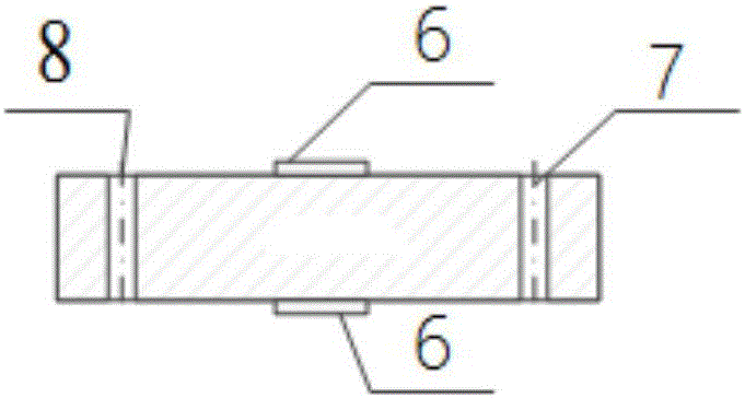
[0044] Such as figure 2As shown, the elastic body base 4 is a strip structure, and one end of the elastic...
Embodiment 3
[0048] Based on the multi-rotor UAV based on tension measurement described in the above-mentioned embodiment one or two, this embodiment provides a flight control method of a multi-rotor UAV based on tension measurement, such as Figure 6 , 7 shown, where Figure 6 It is the schematic diagram of the multi-rotor unmanned aerial vehicle flight control method of the present embodiment, as Figure 7 Shown, the flight control method of this multi-rotor UAV comprises:
[0049] S1, using the deformation measurement sensor to synchronously collect the pulling force of each motor;
[0050] S2, according to the total pulling force of the motor and the torque of the motor in the three directions of X, Y and Z in the body coordinate system, calculate the expected speed of each of the motors and the expected lift of each of the motors;
[0051] S3. Comparing the collected pulling force of each of the motors with the expected lift of each of the motors to obtain a lift error;
[0052] S...
PUM
 Abstract
Description
Claims
Application Information