Clamping parts for easy piece-by-piece extraction from the rack

A piece-by-piece technology for clamping parts, applied in the field of clamping parts, can solve problems such as unreliability, dropping, and difficulty in ensuring that trays are pulled out one by one, achieving the effect of ensuring reliability and reducing strength

Active Publication Date: 2019-11-15
佛山市特福德自动化科技有限公司
View PDF7 Cites 0 Cited by
  • Summary
  • Abstract
  • Description
  • Claims
  • Application Information

AI Technical Summary

Problems solved by technology

But this clamping method is unreliable, the reason is that clamping the tray and extracting the tray are contradictory, the clamping of the tray is clamped by the elastic force of the spring, and sufficient clamping force often makes it difficult to ensure The trays are extracted smoothly, but the lack of clamping force ensures the smooth extraction of the trays, but it also causes the subsequent trays to fall when the trays are extracted, making it difficult to ensure that the trays are pulled out one by one

Method used


Image

  • Clamping parts for easy piece-by-piece extraction from the rack

Examples


Embodiment Construction

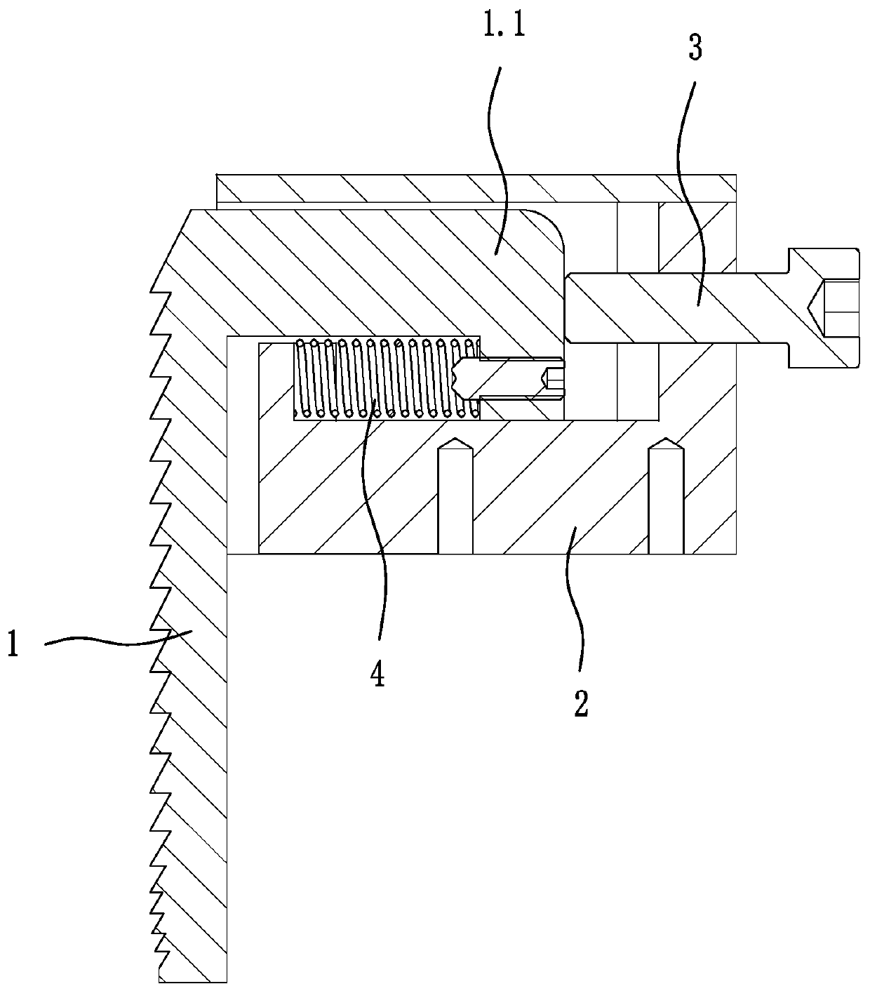
[0009] like figure 1 As shown, a clamping part that is convenient to be pulled out piece by piece from the warehouse rack includes a rack 1 extending downward and a seat 2 for installing the rack 1. The rack 1 has a content accommodated in the seat 2. Set Section 1.1. In the present invention, there is a gap between the rack 1 and the seat body 2 to accommodate the rack 1 to swing perpendicular to the tooth surface, so that only the top of the accommodating part 1.1 and the seat body 2 and the rack There is a gap between the rack and the seat to allow the rack to swing. The base body 2 is equipped with a limiter 3 that touches the end of the accommodating portion 1.1 of the rack 1, and the bottom of the warehouse frame (common components, not shown in the figure) The racks 1 on both sides of the outlet cannot move on both sides, so as long as the installation positions of the clamping parts on both sides are adjusted according to the size specifications of the objects on the...


PUM


Abstract

The invention discloses a clamping part capable of conveniently extracting objects from a storehouse frame one by one. The clamping part comprises a rack extending downwards and a seat body used for installing the rack. The rack is provided with a containing part contained in the seat body. A clearance capable of containing the rack so as to swing perpendicular to a rack face is arranged between the rack and the seat body. The seat body is provided with a limiting part abutting against the end portion of the containing part of the rack. A spring for maintaining the lower end of the rack tend to swing back to the rack face is installed between the containing part and the seat body. The force for clamping the objects can be adjusted only by adjusting the installation positions of clamping parts on the two sides according to the size specification of the objects on the warehouse frame. Due to the spring installed between the containing part and the seat body to maintain the lower end of the rack tend to swing back to the rack face, the clamping force of the objects at the lower end of the rack can be reduced, the clamping force of the objects at the lower ends becomes smaller from top to bottom, the force generated when the objects are extracted is reduced, and the reliability for extracting the objects from the warehouse frame one by one is ensured.

Description

technical field [0001] The present invention relates to the technical field of conveying equipment, and in particular to a clamping part applied to a stacked object shelf to facilitate the extraction of objects from the shelf one by one. Background technique [0002] In the conveying equipment, some objects are stacked on the shelf, and then the suction cup manipulator pulls the objects from the shelf one by one and transports them to the next process. For example, the trays used for packaging products are pre-stacked on the warehouse rack, and there are clamping parts on both sides of the bottom outlet of the warehouse rack, which are used to clamp those trays stacked at the bottom, so that the trays can be stacked on the shelf. On the shelf. When working, the suction cup manipulator under the shelf sucks the tray at the bottom and pulls it away from the shelf, and the trays at the back continue to be clamped on the shelf, and the trays are pulled out one by one to the nex...

Claims


Application Information

Patent Timeline
Patent Type & Authority Patents(China)
IPC IPC(8): B65G59/06
CPCB65G59/061
Inventor 胡景红
Owner 佛山市特福德自动化科技有限公司
Why Eureka
Try Eureka