Roller shutter expansion type rotary kiln adjustable bricklaying machine

A brick laying machine and rotary kiln technology, applied in the field of masonry machinery, can solve the problems of inconvenient operation, unbalanced kiln wall pressure, rising price and cost, etc., and achieve the effects of large adjustable strength, wide application range and simple structure

Inactive Publication Date: 2019-01-11
宜兴瑞泰耐火材料工程有限公司 +1
View PDF1 Cites 0 Cited by
  • Summary
  • Abstract
  • Description
  • Claims
  • Application Information

AI Technical Summary

Problems solved by technology

However, the structure of the bricklaying machine is complex, the operation is inconvenient, and it cannot adapt to the arc structure of different rotary kiln walls, so the application environment is limited
At the same time, in order to exert pressure on more brick bodies, the existing bricklaying machine has a large number of supporting devices, which leads to an increase in price and cost, and at the same time, the pressure on the entire kiln wall is also uneven.

Method used


Image

  • Roller shutter expansion type rotary kiln adjustable bricklaying machine
  • Roller shutter expansion type rotary kiln adjustable bricklaying machine

Examples


Embodiment 1

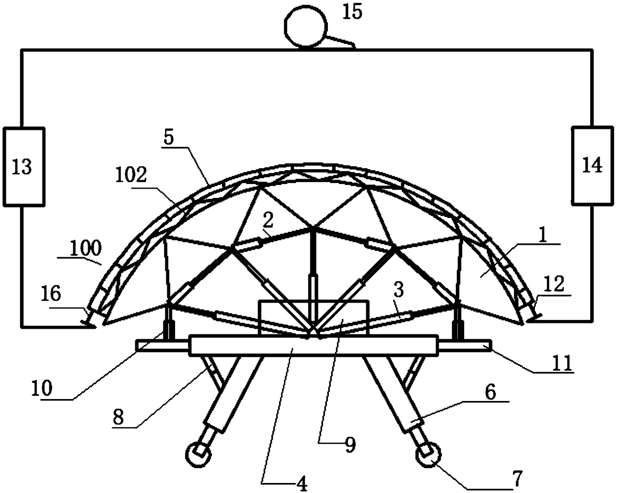
[0023] Such as Figure 1-2 As shown, a rotary kiln adjustable bricklaying machine with an expansion bladder of the present invention includes a bricklaying machine platform 9 and outriggers 6, the outriggers 6 are hydraulic telescopic outriggers, and the bottom of the bricklaying machine platform 9 is provided with two-way hydraulic Adjust the jack 4, the bottom of the two-way hydraulic adjustment jack 4 is connected obliquely with a leg 6, the bottom of the leg 6 is provided with a roller 7, and an adjustable support rod 8 is also arranged between the leg 6 and the main body of the two-way hydraulic adjustment jack 4. The rotary kiln adjustable bricklaying machine also includes a kiln wall support unit. The kiln wall support unit is hinged by a plurality of triangular truss units 1. The outer rods of the triangular truss unit 1 are arc-shaped. They are connected by a one-way telescopic adjustable jack 2, and the two ends of the telescopic adjustable jack 2 are respectively hi...

Embodiment 2

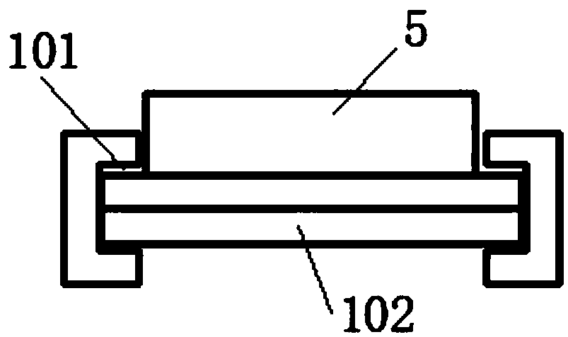
[0025] In this embodiment, the telescopic adjustment jack 2 is a two-way telescopic adjustment jack, and the hydraulic pressure source and the air pressure source corresponding to the two-way hydraulic adjustment jack 4, the telescopic adjustment jack 2, the telescopic adjustment hydraulic rod 3, and the air pressure adjustment pallet device 5 All are connected with the control platform, and the telescopic adjustment control is performed uniformly through the control platform, so as to facilitate the coordinated telescopic control of the kiln wall support unit as a whole. At the same time, the expansion bag 5 is filled with water and connected with a monitoring device to automatically monitor the inflation pressure. The roller blind 102 is also provided with an automatic traction and contraction device, so that it can automatically slide along the slideway 101 and automatically cover the wall tiles. Other structures are with embodiment 1.


PUM


Abstract

The invention relates to a roller shutter expansion type rotary kiln adjustable bricklaying machine. The roller shutter expansion type rotary kiln adjustable bricklaying machine comprises a bricklaying machine platform and supporting legs, a bidirectional hydraulic adjusting jack is arranged at the bottom of the bricklaying machine platform, the roller shutter expansion type rotary kiln adjustablebricklaying machine further comprises a kiln wall supporting unit, the kiln wall supporting unit is formed by hinging a plurality of triangular truss units, every two adjacent corner points on the inner side of each triangular truss unit are connected through a telescopic adjusting jack, and the two ends of each telescopic adjusting jack are correspondingly hinged to the corner points of the adjacent triangular truss units; meanwhile, the inner corners of the triangular truss units at the bottoms of the two sides are connected with telescopic rods extending out of the two sides of the bidirectional hydraulic adjusting jack through supporting rods; the corner points on the inner sides of the triangular truss units are hinged to the bricklaying machine platform through telescopic adjustinghydraulic rods; and a roller shutter expansion device is tightly attached to the outer side of the kiln wall supporting unit, and the roller shutter expansion device comprises slide ways at the two sides, a roller shutter and an expansion bag. The roller shutter expansion type rotary kiln adjustable bricklaying machine is convenient to operate and can adapt to requirements of different-diameter kiln wall radian structures and pressure balance scenes.

Description

technical field [0001] The invention relates to a bricklaying machine, in particular to an adjustable bricklaying machine of a rolling shutter expansion type rotary kiln, which can be used for kiln body masonry and belongs to the technical field of masonry machinery. Background technique [0002] A rotary kiln bricklaying machine is a kind of kiln building machine. CN200982821Y in the prior art relates to a cement rotary kiln bricklaying machine, specifically a movable and adjustable pneumatic bricklaying machine. It includes main support, arch suspension, longitudinal moving vehicle, pneumatic hydraulic cylinder, and longitudinal beam. The two main supports are connected by anti-deformation struts, longitudinal supports, and longitudinal beams. Horizontal planks are installed on the longitudinal beams and placed on the main support. The track at the extension end is equipped with a longitudinal moving vehicle, the track is equipped with a limit rod, the extension end of the...

Claims


Application Information

Patent Timeline
Patent Type & Authority Applications(China)
IPC IPC(8): F27D1/16
CPCF27D1/1621
Inventor 陈松林俞小平王俊涛魏瀚周严敦俞洪芳郭良君邵学军邵一平
Owner 宜兴瑞泰耐火材料工程有限公司
Why Eureka
Try Eureka