Cable rope tension releasing device

A release device and cable rope technology, which is applied in the field of tension release devices, can solve the problems that the release device cannot be adjusted automatically and the tension of the cable rope can be released at will, and achieve the effect of simple structure and reasonable design

Inactive Publication Date: 2017-02-22
杨敏
View PDF0 Cites 1 Cited by
  • Summary
  • Abstract
  • Description
  • Claims
  • Application Information

AI Technical Summary

Problems solved by technology

[0003] Aiming at the deficiencies in the prior art, the present invention provides a cable tension release device to solve the problem that the release device in the prior art cannot be automatically adjusted and the cable tension can be released at will

Method used


Image

  • Cable rope tension releasing device
  • Cable rope tension releasing device
  • Cable rope tension releasing device

Examples


Embodiment

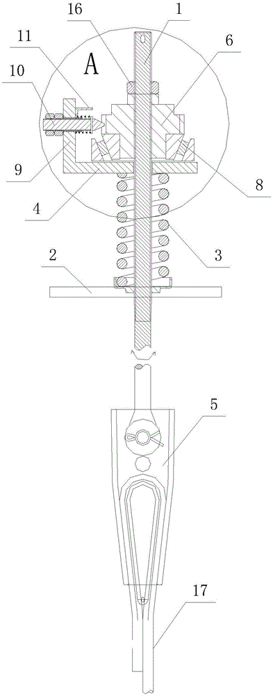
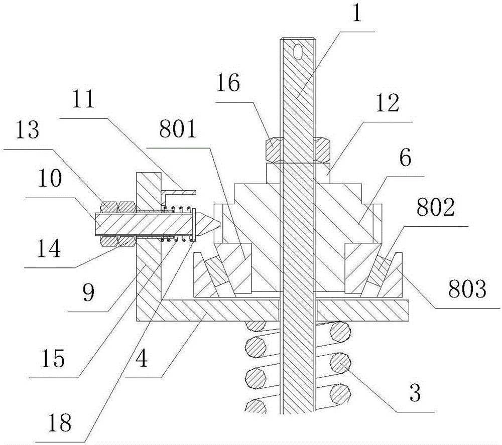
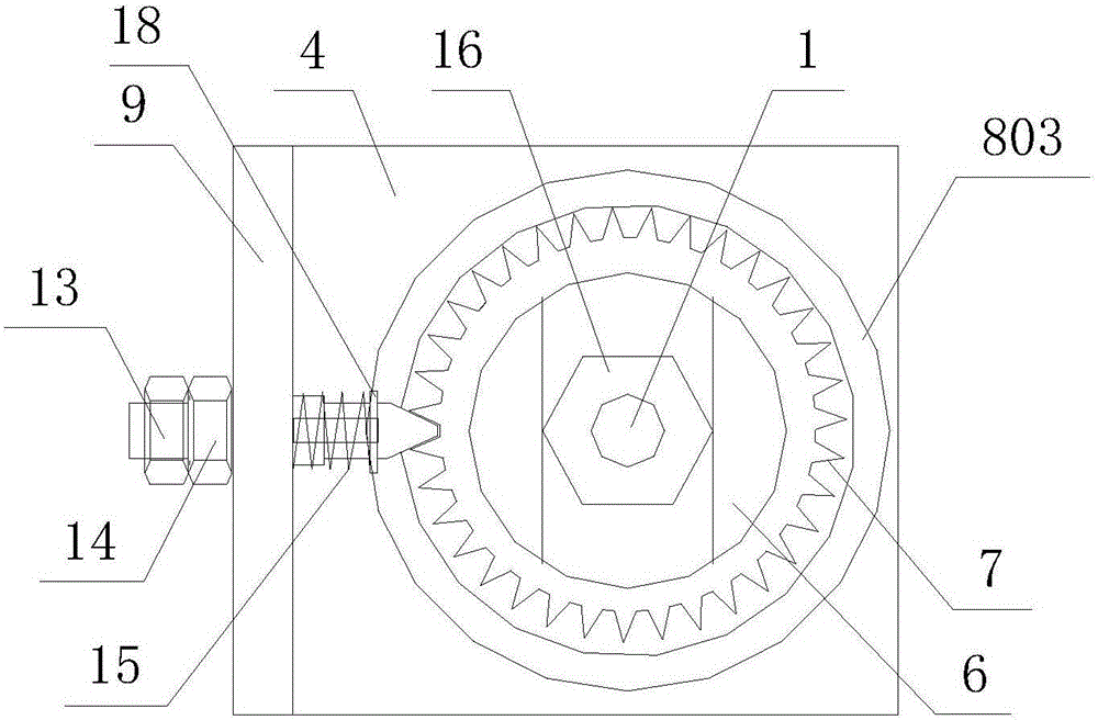
[0015] Such as Figure 1 to Figure 3 As shown, a cable tension release device includes a pull rod 1 and a rope head plate 2 , an elastic element 3 , and a horizontal plate 4 that are sheathed on the pull rod 1 in sequence from bottom to top. The outer surface of the pull rod 1 is provided with external threads, and the bottom end of the pull rod 1 is connected with a rope end taper 5 . The pull rod 1 is covered with a tension release sleeve 6, and the inner hole of the tension release sleeve 6 is provided with an internal thread, so that the tension release sleeve 6 is threadedly connected with the pull rod 1, and a lock is also threaded on the pull rod 1. Nut 16, lock nut 16 is tightened, forms self-locking with described tension releasing bushing 6, just makes tension releasing bushing 6 be fixedly sleeved on described pull rod 1 like this, tension releasing bushing 6 will follow pull rod 1 turn together. The outer circumference of the tension release sleeve 6 is provided ...


PUM


Abstract

The invention discloses a cable rope tension releasing device. The cable rope tension releasing device comprises a pull rod and further comprises a rope head plate, an elastic element, a horizontal plate and a rolling bearing, all of which are sequentially arranged on the pull rod in a sleeving manner from bottom to top. The bottom end of the pull rod is connected with a rope head conical sleeve. The rolling bearing is composed of an inner ring, a rolling piece and an outer ring. A tension releasing shaft sleeve is fixedly arranged on the pull rod in a sleeving manner. A tooth profile is arranged on the outer circumference of the tension releasing shaft sleeve. The outer ring of the rolling bearing and the upper surface of the horizontal plate are fixed. A vertical plate is arranged on the side face of the horizontal plate. The vertical plate is provided with an adjusting screw used for being engaged with the tooth profile of the tension releasing shaft sleeve. The end portion of the adjusting screw is in a conical shape, and the conical end portion of the adjusting screw is in threaded connection with a spring adjusting nut. A clamp lock spring arranged on the adjusting screw in a sleeving manner is arranged between the spring adjusting nut and the vertical plate. By means of the cable rope tension releasing device, rotation control over a cable rope in the horizontal direction is achieved, and control over the stretch-draw releasing force of the cable rope is achieved.

Description

technical field [0001] The invention relates to a tension release device, in particular to a cable tension release device. Background technique [0002] In equipment that uses cable ropes for traction, more than two cable ropes are often used for traction. Due to the change and elongation of the cable tension during the traction process, the rotational torque generated in the cable will rotate the rope head in the direction of torque relaxation, so some of the multiple cables that work together may elongate abnormally. As a result, the cable tension is out of balance. If this state is allowed to develop, the remaining cable rope will produce excessive tension, which will cause premature wire breakage or broken strands in the steel wire of the cable rope, which will bring a greater safety hazard. Therefore, it is necessary to release the tension generated by the cable rope. Judging from the methods currently used, most of the cable rope head assemblies used do not have an ...

Claims


Application Information

Patent Timeline
Patent Type & Authority Applications(China)
IPC IPC(8): B66B7/06
CPCB66B7/06
Inventor 杨敏
Owner 杨敏
Why Eureka
Try Eureka