An in-pipe energy supply device with a turbine

A technology of equipment and leather cups, applied in mechanical equipment, pipe components, pipes/pipe joints/pipe fittings, etc., can solve the problems of poor passability, large workload, limited battery power, etc., to meet complex operation requirements, sufficient power, Powerful access to the effect of convenience

Inactive Publication Date: 2018-05-25
SOUTHWEST PETROLEUM UNIV
View PDF5 Cites 0 Cited by
  • Summary
  • Abstract
  • Description
  • Claims
  • Application Information

AI Technical Summary

Problems solved by technology

At present, this type of in-pipe robot is driven by a battery, and the power of the battery is limited, and the construction work in the tube is heavy and the power consumption is high, so a series of battery packs have to be used for power supply.
Such a long string of in-pipe tools has poor passability, and is prone to damage and jamming in the curved section of the pipe.

Method used


Image

  • An in-pipe energy supply device with a turbine
  • An in-pipe energy supply device with a turbine

Examples


Embodiment Construction

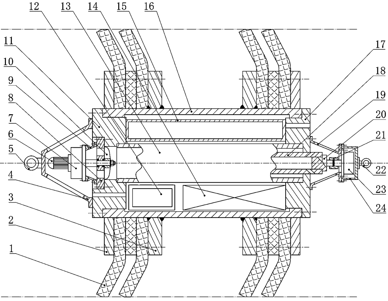
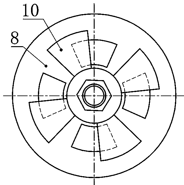
[0015] The present invention is not limited by the following implementation examples, and specific implementation manners can be determined according to the technical solutions of the present invention and actual conditions. Combine below figure 1 , figure 2 The present invention is described below. The positional relationship of up, down, left, right, etc. is based on the attached figure 1 determined by the layout direction.

[0016] The two ends of the cylinder body 16 are respectively equipped with a front end cover 17 and a rear end cover 11 and are fixed with bolts. Two fixing rings 3 are arranged in the middle of the cylinder body 16 and are connected with the cylinder body 16 by welding. The leather cup 1 is installed on the fixing rings 3. Described leather cup 1 is dish-shaped leather cup 1, and baffle plate 2 is arranged on the outer side of leather cup 1, and baffle plate 2 and fixing ring 3 are connected with bolt and leather cup 1 is fixed on the fixing ring 3...


PUM


Abstract

The invention relates to in-pipe energy supply equipment with a turbine for in-pipe construction such as pipeline coating, pipeline shaping and pipeline descaling and provides power to the in-pipe construction equipment. According to the technical scheme, fixed rings are mounted on the outer side of a barrel, and leather cups and baffle rings are mounted; a front end cover and a back end cover are mounted at two ends of the barrel; a turbine motor is mounted between the front end cover and the back end cover; an output shaft of the turbine motor is connected to a hydraulic pump; a protective cover is arranged on the outer side of the hydraulic pump; the hydraulic pump is mounted to the front end cover through a bracket; a valve seat is mounted in a central hole of the back end cover; a back bracket is mounted on the outer side of the valve seat; the motor is mounted to the back bracket through a transmission box; the output shaft of the transmission box penetrates through the valve seat and a valve core is arranged on the end part; an oil tank, a micro-controller and a storage battery are arranged in the barrel; and the oil tank, the micro-controller and the storage battery are connected one another. The equipment provided by the invention can move in a pipe along with an in-pipe robot, so that the equipment can be used for long-distance pipeline construction; by using an in-pipe medium pressure as a power source, power is conveniently gained.

Description

technical field [0001] The invention relates to an in-pipe energy supply equipment with a turbine, which is used for in-pipe construction such as pipeline coating, pipeline shaping, and pipeline descaling, and provides power for the in-pipe construction equipment. Background technique [0002] In the transportation of fluid media, compared with tank transportation, pipeline transportation has the advantages of large transportation volume, continuous transportation, and low operating costs, and is widely used in the transportation of fluids such as oil, water, and gas. Usually, pipelines are laid underground. Under special conditions such as landslides, debris flows, and heavy-load extrusion, the pipelines will be squeezed and deformed, and even large deformations of instability will occur. Someone proposed an in-pipe repair scheme for deformed pipelines, which is more efficient and economical than the pipe cutting replacement scheme, and has advantages. This solution uses t...

Claims


Application Information

Patent Timeline
Patent Type & Authority Patents(China)
IPC IPC(8): F16L55/28
CPCF16L55/28
Inventor 梁政肖瑶何虹钢鲁鑫钟丽群张梁
Owner SOUTHWEST PETROLEUM UNIV
Why Eureka
Try Eureka