Display device and 2D display mode realization method

A technology of a display device and a realization method, which is applied in the field of 2D/3D display, can solve the problems such as the electro-optic refractive index is not strictly phased, achieve the effect of alleviating the high requirements of the manufacturing process, overcome the lens residue, and achieve good 2D display effect

Inactive Publication Date: 2017-02-22
ZHANGJIAGANG KANGDE XIN OPTRONICS MATERIAL
View PDF5 Cites 2 Cited by
  • Summary
  • Abstract
  • Description
  • Claims
  • Application Information

AI Technical Summary

Problems solved by technology

[0006] The main purpose of this application is to provide a display device and a method for realizing its 2D display mode, so as to solve the problem in the prior art that the refractive index of the material of the visual separation structure layer is not strictly equal to the refractive index of the electro-optic in the 2D display mode

Method used


Image

  • Display device and 2D display mode realization method
  • Display device and 2D display mode realization method

Examples


Embodiment 1

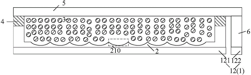
[0042] The structure of the display device is as figure 1 As shown, wherein, the lenticular lens film is a concave lens film, the material of the film has a refractive index n, the electro-optic material is a liquid crystal molecule, and the minimum and maximum values ​​of the refractive index are respectively n o (i.e. n 1 ) and n e (i.e. n 2 ), where n-n o e -n.

[0043] The voltage applied to the display device is 0V, ie V OFF =0V, at this time, the direction of the optical axis of the liquid crystal molecules is parallel to the polarization direction of the image light, so that the refractive index of the liquid crystal molecules is felt by the abnormal light refractive index n e , when the image light passes through the concave lens in the plano-concave lens film, it feels the effect of the convex lens to realize 3D display.

[0044] The applied voltage of the display device is adjusted so that the effective refractive index of the liquid crystal molecules is strict...

Embodiment 2

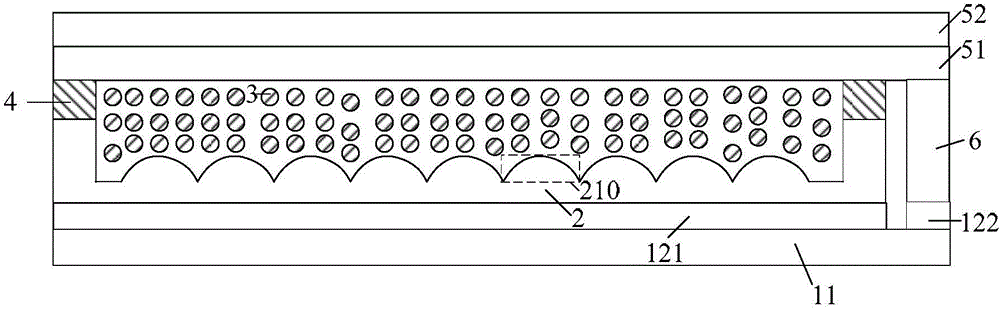
[0046] The structure of the display device is as figure 2 As shown, wherein the lenticular lens film is a convex lens film, the material of the film has a refractive index of n, the electro-optical material is a liquid crystal molecule, and the minimum and maximum values ​​of the refractive index are respectively n o (i.e. n 1 ) and n e (i.e. n 2 ), where n e -no .

[0047] The voltage applied to the display device is V, ie V ON , at this time, the direction of the optical axis of the liquid crystal molecules is parallel to the thickness direction of the first substrate, while the polarization direction of the image light is still perpendicular to the paper surface, and the direction of the optical axis of the liquid crystal molecules is perpendicular to the polarization direction of the image light, so that the liquid crystal molecules The refractive index of ordinary light is felt as the refractive index n e , when the image light passes through the convex lens in the...


PUM


Abstract

The invention provides a display device and a 2D display mode realization method. The display device comprises a visual scene separation structural layer and an electro-optical material. The realization method comprises the steps of applying a voltage to the display device and adjusting the voltage to V1 till the refractive index of the electro-optical material is equal to that of the visual scene separation structural layer, wherein the display device is in a 2D display mode at the moment. Through adoption of the realization method, the phenomenon that requirements on the refractive index setting of the visual scene separation structural layer and a preparation process of the display device are high in the prior art is relieved, and a lens residue phenomenon caused by non-strictly equal refractive indexes of the electro-optical material and the visual scene separation structural layer in the prior art is overcome; therefore, the 2D display effect of the display device is good.

Description

technical field [0001] The present application relates to the field of 2D / 3D display, in particular, to a display device and a method for realizing the 2D display mode thereof. Background technique [0002] In the prior art, in a 2D / 3D switchable display device, the combination of a visual separation structure layer and an electro-optical material (such as a liquid crystal material) is used to realize switching between 2D mode and 3D mode. Electro-optic materials have different refractive indices under different voltages. When the voltage V between the electrodes of the display device OFF , its refractive index n 1 , at V ON , its refractive index n 2 . The refractive index of the visual separation structure layer material needs to be equal to n 1 or n 2 , so as to realize the 2D display of the display device. [0003] When the refractive index of the view separation structure layer is equal to n 1 , and when the refractive index of the electro-optic material is also...

Claims


Application Information

Patent Timeline
Patent Type & Authority Applications(China)
IPC IPC(8): G02F1/29G02F1/1335G02B27/22
CPCG02B30/00G02F1/133526G02F1/29
Inventor 林明彦张晶范延江曾凡初
Owner ZHANGJIAGANG KANGDE XIN OPTRONICS MATERIAL
Why Eureka
Try Eureka