
The pinch structure of the handstand machine

An inversion machine and foot clamping technology, which is applied to gymnastic equipment, sports accessories, stilts, etc., and can solve problems such as users falling

Active Publication Date: 2019-01-18
BETO ENG & MARKETING
View PDF8 Cites 0 Cited by
  • Summary
  • Abstract
  • Description
  • Claims
  • Application Information

AI Technical Summary

Problems solved by technology

Although the user's feet are clamped and then turned upside down, if the user accidentally touches the adjustment mechanism by mistake, the movable foot cover will open, causing the user to fall. Dangerous situation occurs

Method used


Image

  • The pinch structure of the handstand machine
  • The pinch structure of the handstand machine
  • The pinch structure of the handstand machine

Examples


Embodiment Construction

[0043] In order to further explain the technical solution of the present invention, the present invention will be described in detail below through specific examples.

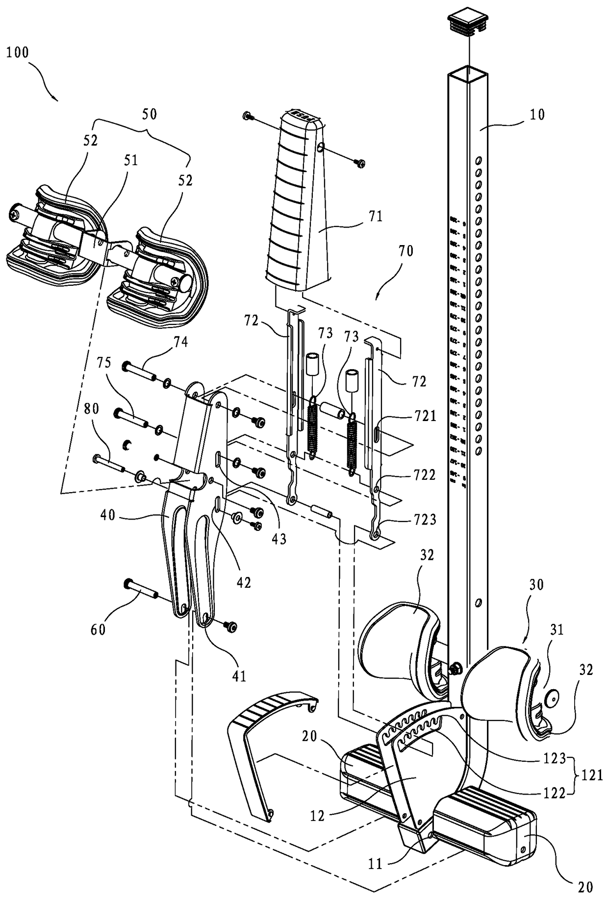
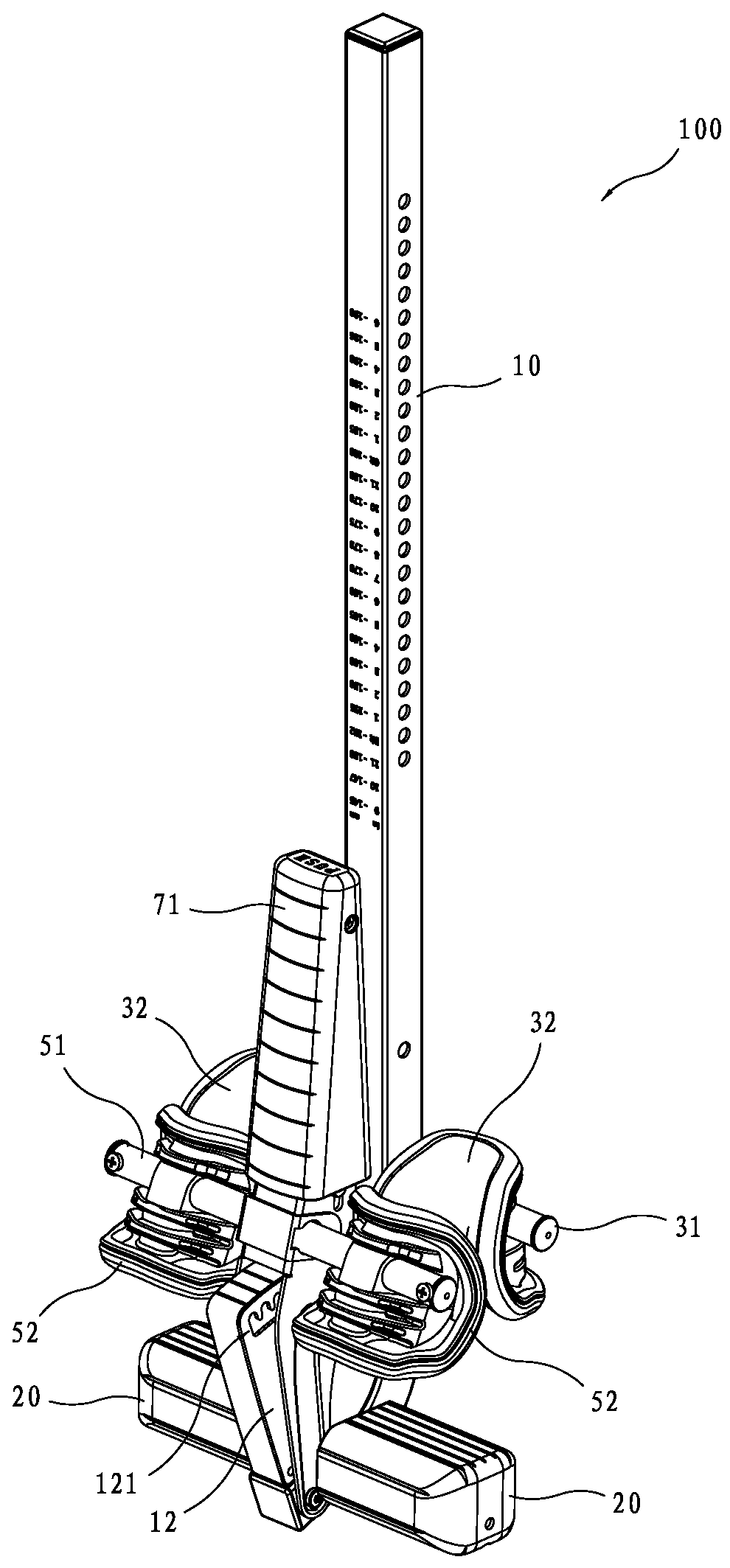
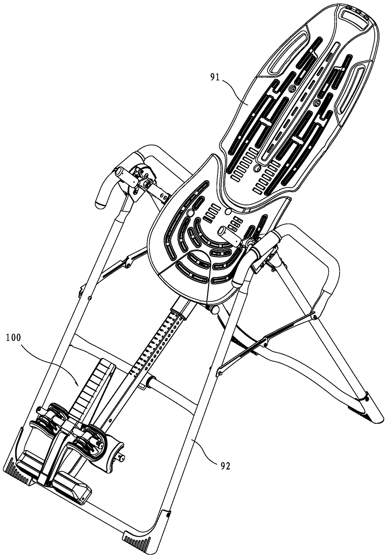
[0044] see Figure 1 to Figure 12 As shown, a clamping foot structure 100 of a handstand machine provided by a preferred embodiment of the present invention mainly includes a foot bar 10, two pedals 20, a fixed foot set 30, an adjustment seat 40, and a movable foot Set 50, a pivot shaft 60, an elastic positioning unit 70 and a positioning shaft 80, wherein:

[0045] see Figure 1 to Figure 4 , the bottom end of the foot bar 10 has a pivot hole 11 radially penetrating through it, the side of the foot bar 10 adjacent to the bottom end has a positioning plate 12, and the positioning plate 12 has a positioning groove 121, the positioning groove 121 There is an active area 122 and several positioning areas 123 connected to the active area 122 and located on the same side of the active area 122 , and the positionin...


PUM


Abstract

The invention discloses a clamping leg structure of an inversion machine. The clamping leg structure comprises a leg rod, a fixed leg set fixedly connected to the leg rod, an adjusting seat, a movable leg set fixedly connected to the adjusting seat, a pivoting shaft, an elastic poisoning unit and a poisoning shaft; the leg rod is provided with a pivot hole and a positioning groove, and the positioning groove is provided with an active area and a positioning area; the adjusting seat is provided with a pivoting elongated hole and a positioning elongated hole; the pivoting shaft penetrates through the pivoting elongated hole and the pivot hole; the elastic poisoning unit is provided with a linkage hole, is arranged on the adjusting seat and can perform reciprocating displacement between a positioning position and an adjusting position; the positioning shaft penetrates through the positioning elongated hole, the linkage hole and the positioning groove; the positioning shaft is linked by the elastic poisoning unit; when the leg rod is inverted, the adjusting seat moves downwards along the pivoting elongated hole, the positioning elongated hole is not superposed with the active area at the moment, and the positioning shaft cannot move to the active area from the positioning area, so that the adjusting seat cannot pivot opposite to the leg rod to achieve the effect of better safety.

Description

technical field [0001] The invention relates to an inversion machine, in particular to a clamping foot structure of the inversion machine. Background technique [0002] Inversion machine is a kind of machine that can hang the user upside down to promote the user's blood circulation and relax muscles. [0003] However, the current common inversion machine is mainly clamped on the user's foot (ankle) by a fixed foot cover and a movable foot cover, and the movable foot cover can be controlled by an adjustment mechanism to pivot, and then achieve opening. and clamping effect. Although the user's feet are clamped and then turned upside down, if the user accidentally touches the adjustment mechanism by mistake, the movable foot cover will open, causing the user to fall. A dangerous situation has occurred. Contents of the invention [0004] The object of the present invention is to provide a relatively safe clamping foot structure for an inversion machine, so as to avoid the d...

Claims


Application Information

Patent Timeline
Patent Type & Authority Patents(China)
IPC IPC(8): A63B26/00
Inventor 王罗平
Owner BETO ENG & MARKETING
Learn More