
Air-filling equipment for making foam plastics

A foamed plastics and equipment technology, which is applied to the field of gas filling equipment for foamed plastics production, can solve the problem of difficult to know whether or not enough gas has been added, and achieves the effect of simple operation and improved automation.

Active Publication Date: 2018-10-16
武汉荆楚普泰新材料有限公司
View PDF3 Cites 0 Cited by
  • Summary
  • Abstract
  • Description
  • Claims
  • Application Information

AI Technical Summary

Problems solved by technology

[0005] In order to overcome the shortcoming that it is difficult to know whether enough gas has been added in the present artificial gas-filling method, the technical problem to be solved by the invention is to provide a foam plastics filling gas filling method that can well know whether the gas is filled. gas equipment

Method used


Image

  • Air-filling equipment for making foam plastics
  • Air-filling equipment for making foam plastics
  • Air-filling equipment for making foam plastics

Examples


Embodiment 1

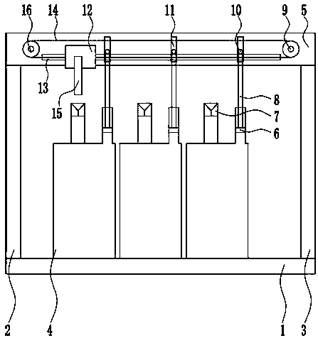
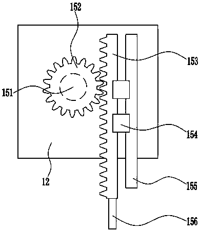
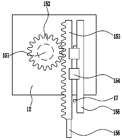
[0028] A kind of air-filling equipment for making foam plastics, such as Figure 1-4 As shown, it includes bottom plate 1, left frame 2, right frame 3, storage tank 4, mounting plate 5, piston 6, rubber plug 7, connecting rod 8, first fixed pulley 9, first travel switch 10, first Slider 12, first slide rail 13, pull wire 14, elevating device 15 and second fixed pulley 16, bottom plate 1 top left side is welded with left frame 2, bottom plate 1 top right side is welded with right frame 3, left frame 2 and right The top of frame 3 is welded with mounting plate 5, evenly has a word hole 11 on the mounting plate 5, and the front side of mounting plate 5 is welded with the first fixed pulley 9 and the second fixed pulley 16 through the bracket left and right symmetry, the first fixed pulley 9 and the second fixed pulley The two fixed pulleys 16 are rotatable, the first fixed pulley 9 and the second fixed pulley 16 are wound with a backguy 14, and the lower part of the front side of...


PUM


Abstract

The invention relates to aeration equipment, in particular to aeration equipment for foam plastic manufacturing. The technical problem to be solved by the invention is to provide the aeration equipment for foam plastic manufacturing capable of preferably knowing if gas is fully filled. In order to solve the technical problem, the invention provides the aeration equipment for foam plastic manufacturing. The aeration equipment for foam plastic manufacturing comprises a baseplate, a left frame, a right frame, a storage tank, a mounting plate, a piston, a rubber plug, a connecting rod, a first fixed pulley, a first travel switch, a first slide block, a first slide rail and the like; the left frame is welded on the left side of the top of the baseplate; the right frame is welded on the right side of the top of the baseplate; the mounting plate is welded at the tops of the left frame and the right frame; and horizontal holes are uniformly formed in the mounting plate. The aeration equipment controls clockwise rotation and anticlockwise rotation of a rotating motor by using contact and no contact between the first travel switch and the first slide block; and the first travel switch achieves the effect of stop the first slide block to move to the right side.

Description

technical field [0001] The invention relates to an air-filling device, in particular to an air-filling device for making foam plastics. Background technique [0002] Foam plastic is a dispersion composed of gaseous substances as the dispersed phase and solid resin as the dispersion medium. It is a type of plastic product with many pores. Foam plastic has the advantages of light weight, low thermal conductivity, low hygroscopicity, good elasticity, high specific strength, sound insulation and heat insulation. Therefore, it is widely used as sound-absorbing and heat-insulating, anti-freezing and heat-insulating, cushioning and shock-proof, and lightweight structural materials, and is also widely used in transportation, housing construction, packaging, daily necessities, and national defense and military industries. [0003] When making foam plastics, gas needs to be injected, and the current gas filling method is still mainly manual. At present, it is difficult to know whethe...

Claims


Application Information

Patent Timeline
Patent Type & Authority Patents(China)
IPC IPC(8): B29C67/20
CPCB29C67/20
Inventor 钱嘉良
Owner 武汉荆楚普泰新材料有限公司
Learn More