Anti-wave device and working method for floating signal tower

A wave-proof and signal tower technology, applied in the field of signal towers, can solve problems such as threats to equipment and personnel safety, and poor mooring environment, and achieve the effects of convenient installation and transportation, improved mooring environment, and reduced impact on normal operations

Active Publication Date: 2018-06-08
SHANDONG UNIV OF SCI & TECH
View PDF6 Cites 0 Cited by
  • Summary
  • Abstract
  • Description
  • Claims
  • Application Information

AI Technical Summary

Problems solved by technology

However, due to the strong winds and waves, fast ocean currents and harsh mooring environment in the deep sea area, various marine environmental forces inevitably cause the signal tower to move, sway, float and sink, and even threaten the safety of equipment and personnel. Floating signal towers must withstand the test of such a complex and extreme ocean environment

Method used


Image

  • Anti-wave device and working method for floating signal tower
  • Anti-wave device and working method for floating signal tower
  • Anti-wave device and working method for floating signal tower

Examples


Embodiment 1

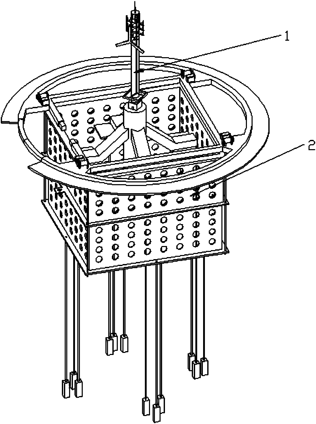
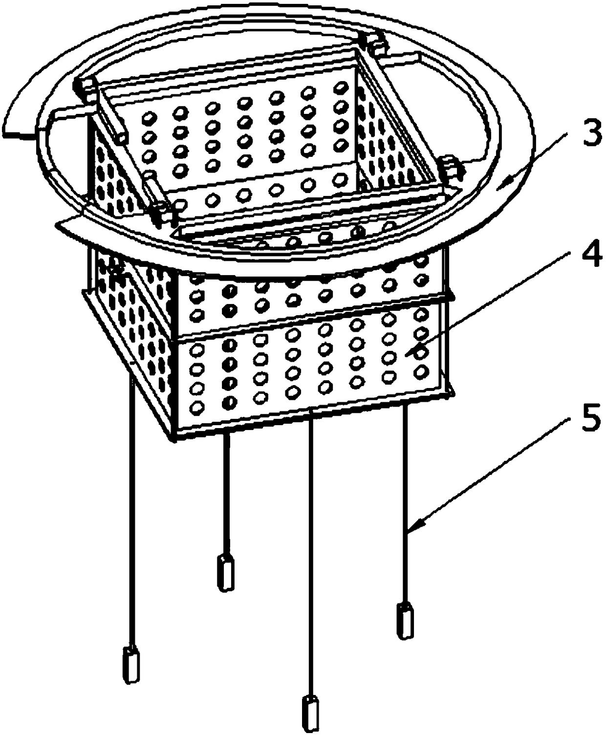
[0039] An anti-wave device for floating signal towers, such as Figure 2.1 As shown, it includes the anti-wave device buoy 3, the anti-wave system 4 and the tension leg system 5 connected sequentially from top to bottom, such as Figure 2.3As shown, the wave-proof tube system 4 includes a primary wave-proof tube 19, a secondary wave-proof tube 22 that can move up and down and is sleeved in the primary wave-proof tube 19, the primary wave-proof tube 19 and the secondary wave-proof tube 22 up and down There is no cover, and several anti-wave holes 23 are provided on the walls of the primary wave-proof barrel 19 and the secondary wave-proof barrel 22 .

[0040] The anti-wave device is arranged on the periphery of the signal tower 1, such as figure 1 As shown, the anti-wave device buoy 3 makes the anti-wave device float on the sea surface, controls the expansion degree of the secondary anti-wave cylinder 22, changes the size of the anti-wave hole 23, controls the flow rate of the...

Embodiment 2

[0054] The working method of the anti-wave device described in embodiment 1, the specific steps include:

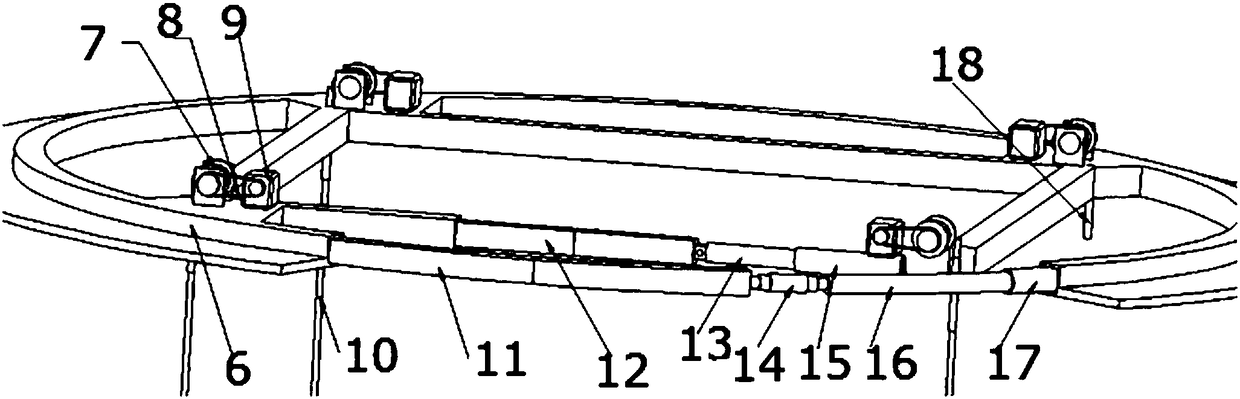
[0055] (1) The anti-wave device is transported around the signal tower 1 by a transport ship, the pile anchor 25 is fixed on the seabed, and the anti-wave device is floated around the signal tower 1 by the buoy 6 and the tension leg system 5;

[0056] (2) Control the rotation of the drum 7 through the motor 9, control the movement of the limit screw 21 through the traction rope 10, and control the expansion degree of the secondary anti-wave cylinder 22, so that the anti-wave device can adapt to different working environments;

[0057] (3) When a working ship enters and exits the signal tower 1, the expansion and contraction of the buoy outer retaining ring 11 and the buoy inner retaining ring 12 are respectively controlled by controlling the outer ring hydraulic cylinder 17 and the inner ring hydraulic cylinder telescopic cylinder 15, so that the anti-wave device is in the...


PUM


Abstract

The invention relates to an anti-wave device for a floating type signal tower and a working method thereof. The anti-wave device comprises an anti-wave device buoy, an anti-wave drum system and a tension leg system which are successively connected from top to bottom, wherein the anti-wave drum system comprises a first level anti-wave drum and a second level anti-wave drum which is vertically moveable sleeved in the first level anti-wave drum; the upper and lower ends of both the first level anti-wave drum and the second level anti-wave drum are free from cover; a plurality of anti-wave holes are formed in the drum walls of the first level anti-wave drum and the second level anti-wave drum. The anti-wave device is arranged on the periphery of the signal tower and is arranged as a tension leg type floating device, so that the impacts of gale, wave and flow to the signal tower platform can be effectively relieved, the influence of a storm load on the normal operation of the signal tower is reduced, the mooring environment is improved and the ocean floating pollutants are prevented from entering into the signal tower platform.

Description

technical field [0001] The invention relates to an anti-wave device for a floating signal tower and a working method thereof, belonging to the technical field of signal towers. Background technique [0002] The signal tower is a signal transmitting device established by the network operator, which plays the role of a repeater in the communication transmission, and refers to the transmission of information between the communication switching center and the mobile phone terminal in a certain radio coverage area. Transmitting radio transceiver station. After the popularity of wireless cities, signal towers have become the base point for signal transmission of urban WIFI. Signal towers are widely used in the mainland, and there will be signal coverage of signal towers in coastal areas, while in remote sea areas and areas far away from islands, due to the objective condition of lack of land, there are no signal towers, so there is almost no wireless network. It is very inconven...

Claims


Application Information

Patent Timeline
Patent Type & Authority Patents(China)
IPC IPC(8): B63B21/50B63B35/44
CPCB63B21/502B63B35/44Y02A30/30
Inventor 万丽荣尹广俊杨扬王志文王通高魁东赵森庆胡延清刘鹏于鹏飞
Owner SHANDONG UNIV OF SCI & TECH
Why Eureka
Try Eureka