
Laser gyroscope zero bias magnetic field sensitivity test and magnetic zero bias temperature compensation method

A magnetic field sensitivity, laser gyro technology, applied in the fields of inertial navigation, guidance and control, to achieve the effect of improving accuracy and compensating zero bias error

Inactive Publication Date: 2019-09-27
NAT UNIV OF DEFENSE TECH
View PDF3 Cites 0 Cited by
  • Summary
  • Abstract
  • Description
  • Claims
  • Application Information

AI Technical Summary

Problems solved by technology

[0005] The purpose of the present invention is to provide the test method of the zero bias magnetic field sensitivity of the laser gyroscope under different temperature conditions for the characteristics of the magnetically induced zero bias of the laser gyroscope, and propose a temperature for the magnetically induced zero bias of the laser gyroscope Compensation method to improve the accuracy of the laser gyroscope and its strapdown inertial navigation system in complex temperature and electromagnetic working environments

Method used


Image

  • Laser gyroscope zero bias magnetic field sensitivity test and magnetic zero bias temperature compensation method
  • Laser gyroscope zero bias magnetic field sensitivity test and magnetic zero bias temperature compensation method
  • Laser gyroscope zero bias magnetic field sensitivity test and magnetic zero bias temperature compensation method

Examples


Embodiment Construction

[0044] The specific embodiments of the present invention will be further described below in conjunction with the accompanying drawings.

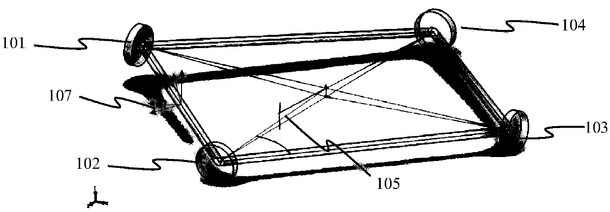
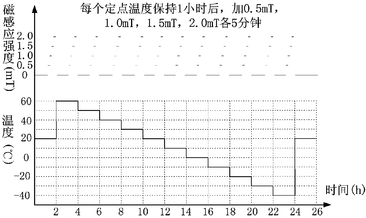
[0045] Take the magnetic field sensitivity test and magnetic-induced zero-bias temperature compensation method of a 90-type two-frequency machine-jittered laser gyroscope as an example, as shown in figure 2 As shown, the method includes the following steps:

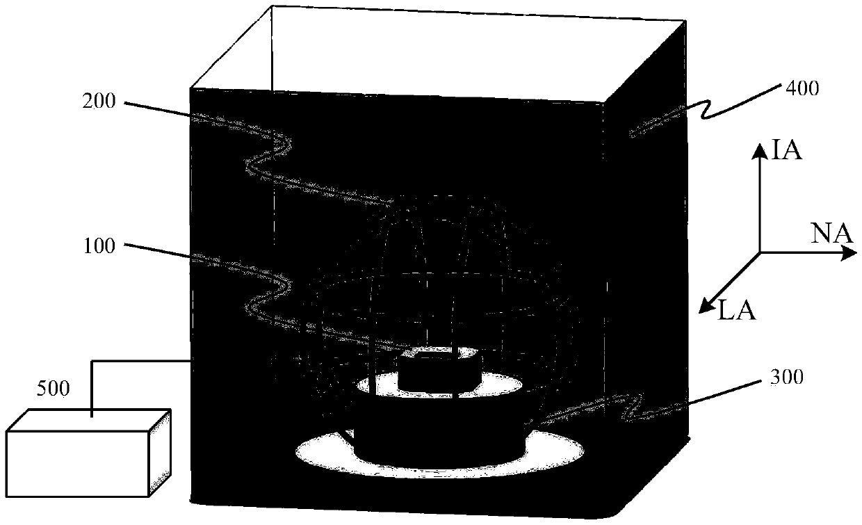
[0046] Step 1. Measure the zero-bias magnetic field sensitivity of the 90-type two-frequency machine-shaking laser gyroscope 100 under different temperature conditions:

[0047] S1.1. Install the three-dimensional Helmholtz coil 200 in the temperature change test chamber 400;

[0048] S1.2. Install the 90-type two-frequency machine-shaking laser gyroscope 100 on the test tool 300;

[0049] S1.3. Place the 90-type two-frequency machine-shaking laser gyroscope 100 installed on the test tool 300 in the three-dimensional Helmholtz coil 200, and connect the sensitive axis IA of the 90-typ...


PUM


Abstract

The invention relates to a zero-offset magnetic field sensitivity testing method of a laser gyroscope and a magnetic zero-offset temperature compensating method of the laser gyroscope, and belongs to the field of inertial navigation, guidance and control. According to the zero-offset magnetic field sensitivity testing method disclosed by the invention, an original zero-offset magnetic field sensitivity testing method of the laser gyroscope is improved and supplemented, and the zero-offset magnetic field sensitivities of the laser gyroscope under different magnetic induction intensities and different temperature conditions can be reflected, so that the magnetic zero-offset performance of the laser gyroscope can be comprehensively evaluated; based on the zero-offset magnetic field sensitivity testing method, the invention provides the magnetic zero-offset temperature compensating method of the laser gyroscope, and magnetic zero offset of the laser gyroscope is compensated by utilizing the tested zero-offset magnetic field sensitivity characteristics of the laser gyroscope under different magnetic induction intensities and different temperature conditions, so that the performance requirements of the laser gyroscope under different temperatures and different electromagnetic working environments can be met, and the navigation accuracy of an inertial navigation system of the laser gyroscope can be increased.

Description

technical field [0001] The invention relates to a method for testing the zero-bias magnetic field sensitivity of a laser gyroscope and a magnetic-induced zero-bias temperature compensation method for a laser gyroscope, belonging to the fields of inertial navigation, guidance and control. Background technique [0002] The laser gyroscope is a device for measuring angular rate and angle based on the Sagnac effect and composed of a ring laser resonator. Its outstanding advantages include: large measurement range, low cost, insensitivity to vibration and shock, fast startup, high reliability, low power consumption, etc. It has been widely used in various fields such as aerospace, land vehicles, ships and submarines. Among the error sources of the laser gyroscope, the magnetic bias is a comprehensive error caused by machining, assembly and debugging, and the properties of the material itself, especially for the laser gyroscope with a square resonant cavity, the closed ring cavity...

Claims


Application Information

Patent Timeline
Patent Type & Authority Patents(China)
IPC IPC(8): G01C25/00
Inventor 李耿龙兴武高春峰王琦张鹏飞谢元平魏国于旭东
Owner NAT UNIV OF DEFENSE TECH
Learn More