Layering-preventing structure for TSOP packing lead frame

A technology of encapsulating leads and layered structures, applied in electrical components, electrical solid devices, circuits, etc., can solve the problems of product reliability, poor shrinkage force, and poor stress resistance, so as to ensure vacuum fixation and increase impact. The effect of cutting area, reducing possibility

Active Publication Date: 2017-03-08
SUZHOU PUFUSI INFORMATION SCI & TECH
View PDF6 Cites 0 Cited by
  • Summary
  • Abstract
  • Description
  • Claims
  • Application Information

AI Technical Summary

Problems solved by technology

[0002] TSOP packaging form is a very widely used packaging form in IC packaging at present. The lead frame used is copper. If the whole piece of copper is punched into a hollow form, the overall stress resistance will become poor and easy to deform. Tape will be pasted on the frame to keep its structure stable. Due to cost reasons, this layer of tape will usually be made into separate strips. In addition to fixing the lead frame, the wafer IC is also provided. When packaging, the wafer IC is attached to the frame fixing tape; the gap between the lead frame and the wafer IC will cause the lower part of the wafer IC to be suspended due to the gap between the frame fixing tape and the lead frame. The wire bonding process has high requirements on the fixing accuracy of the working materials, so the frame under the wafer IC should be sucked by the vacuum suction plate of the wire bonding machine as much as possible to reduce the up and down jump of the wafer IC during operation, which will require the lead frame to be fixed as much as possible. It is possible to reserve a large area of ​​uncut area for the suction plate to absorb, and the large area of ​​copper sheet will easily cause the independent area between it and the resin to be too large during injection molding, resulting in a large shrinkage difference due to the different shrinkage rates of different materials. Easy delamination causes product reliability problems

Method used


Image

  • Layering-preventing structure for TSOP packing lead frame
  • Layering-preventing structure for TSOP packing lead frame
  • Layering-preventing structure for TSOP packing lead frame

Examples


Embodiment Construction

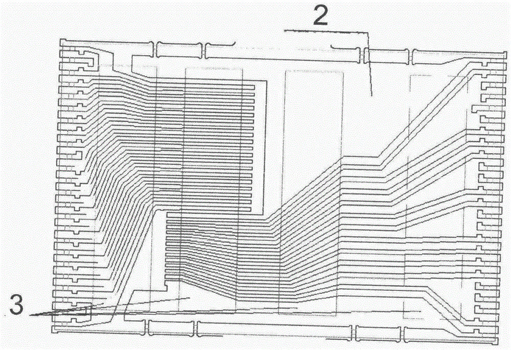
[0014] Such as figure 1 with figure 2 Shown, the contrast of the anti-delamination structure of the TSOP package form lead frame of the present invention and the existing layered structure is: the large-area copper sheet area (such as figure 1 As shown), it can be well absorbed by the suction plate of the wire bonding machine, but it will cause the problem of delamination in the injection molding. The body produces a large stress difference due to different shrinkage rates, resulting in delamination (such as figure 2 shown).

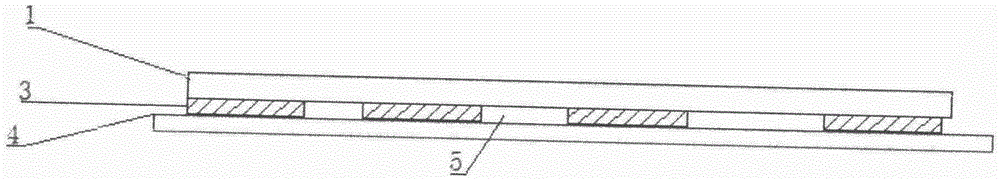
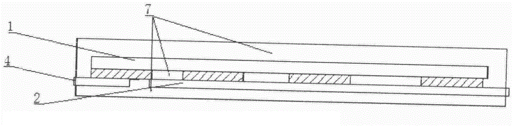
[0015] Such as image 3 with Figure 4 As shown, the TSOP package lead frame anti-delamination structure of the present invention includes wafer IC1, adhesive tape 3, lead frame 4 and floating area 5, and a large-area copper area 2 is provided on the lead frame below the wafer IC1 position , the wafer IC1 is covered with adhesive tape 3, the suspended area 4 is arranged between the adhesive tapes 3, the lead frame 4 is arranged on the bottom surfa...


PUM


Abstract

The invention relates to a layering-preventing structure for a TSOP packing lead frame. The layering-preventing structure comprises a wafer IC, adhesive tapes, a lead frame and a suspending region, wherein a large-area copper region is arranged on the lead frame; the strip-shaped adhesive tapes cover the position below the wafer IC; the suspending region is arranged between the adhesive tapes; the lead frame is arranged on the bottom surfaces of the adhesive tapes; square copper sheets are arranged on the large-area copper region in the position of wafer IC of the lead frame; the residual large-area copper region of the large-area copper region is provided with hollow-outs; resin is arranged in the hollow-outs in an injection molding manner; and the resin passes through the lead frame to be combined with the wafer. According to the technical scheme, a vacuum chuck structure is designed on the lead frame, and a punching and cutting area in the residual large-area copper region is enlarged while the area of the chuck is ensured, so that existence of the large-area copper sheets is reduced.

Description

technical field [0001] The invention discloses an anti-delamination structure of a TSOP packaging lead frame. Background technique [0002] TSOP packaging form is a very widely used packaging form in IC packaging at present. The lead frame used is copper. If the whole piece of copper is punched into a hollow form, the overall stress resistance will become poor and easy to deform. Tape will be pasted on the frame to keep its structure stable. Due to cost reasons, this layer of tape will usually be made into separate strips. In addition to fixing the lead frame, the wafer IC is also provided. When packaging, the wafer IC is attached to the frame fixing tape; the gap between the lead frame and the wafer IC will cause the lower part of the wafer IC to be suspended due to the gap between the frame fixing tape and the lead frame. The wire bonding process has high requirements on the fixing accuracy of the working materials, so the frame under the wafer IC should be sucked by the ...

Claims


Application Information

Patent Timeline
Patent Type & Authority Applications(China)
IPC IPC(8): H01L23/495H01L23/31
Inventor 凡会建李文化彭志文
Owner SUZHOU PUFUSI INFORMATION SCI & TECH
Why Eureka
Try Eureka