Zoom lens and camera

A zoom lens and lens technology, applied in the field of camera devices and zoom lenses, can solve the problems of small wide-angle end, reduced F value, large F value at telephoto end, etc.

Active Publication Date: 2020-07-03
FUJIFILM CORP
View PDF6 Cites 0 Cited by
  • Summary
  • Abstract
  • Description
  • Claims
  • Application Information

AI Technical Summary

Problems solved by technology

[0005] However, in a zoom lens with such a structure, it is difficult to reduce the F value in the entire zoom range with a small number of lenses. In the zoom lens of Patent Document 1, the F value at the wide-angle end is very small and the F value at the telephoto end is very small. Questions like value

Method used


Image

  • Zoom lens and camera
  • Zoom lens and camera
  • Zoom lens and camera

Examples


Embodiment 1

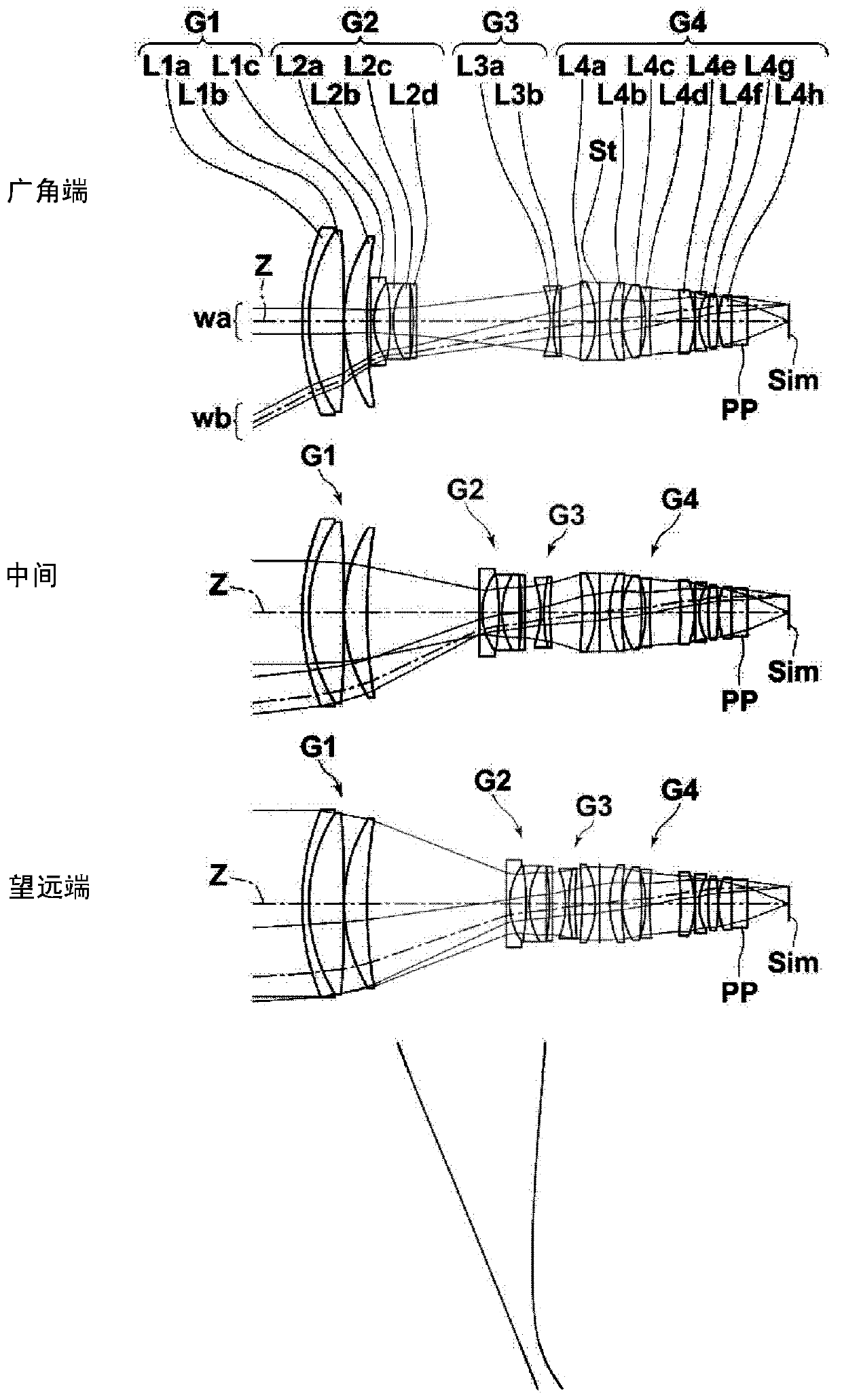
[0168] The zoom lens of Example 1 includes in order from the object side: a first lens group G1 composed of three lenses, lens L1a to lens L1c; a second lens group G2, composed of four lenses, lens L2a to lens L2d; The third lens group G3 composed of two lenses, lens L3a and lens L3b; and the fourth lens group G4 composed of eight lenses, lens L4a to lens L4h.

[0169] Table 1 shows basic lens data of the zoom lens of Example 1, Table 2 shows data related to various factors, and Table 3 shows data related to varying face spacing. Hereinafter, although Example 1 is taken as an example and the meaning of the symbol in a table is demonstrated, it is basically the same about Examples 2-7.

[0170] In the lens data in Table 1, the column of the surface number shows the surface number of the constituent element closest to the object side as the first and increases in order toward the image plane side, and the column of the radius of curvature shows each surface The radius of curvat...
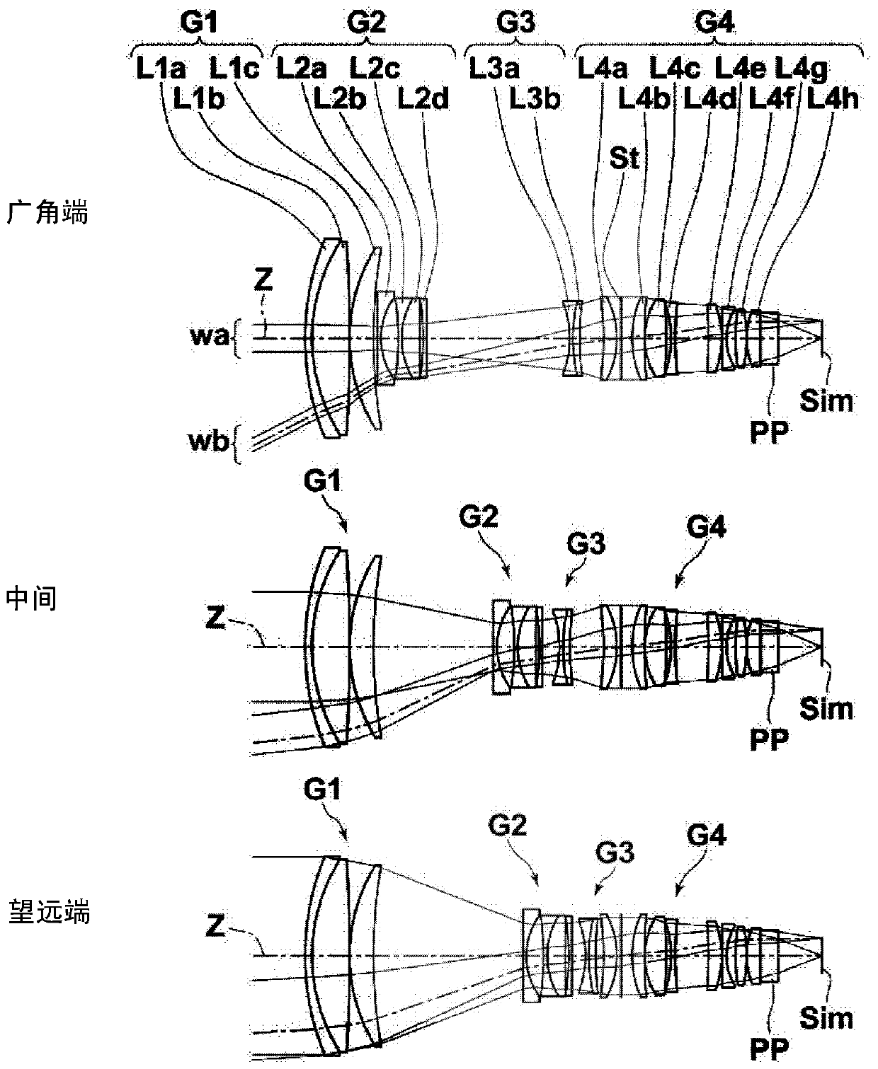
Embodiment 2

[0186] Example 2 Lens data

[0187] face number radius of curvature face spacing nd vd 1 63.42210 1.6000 2.001 25.46 2 43.88040 8.5716 1.595 67.73 3 -368.22272 0.0100 4 41.66604 5.4915 1.497 81.61 5 127.26898 DD[5] 6 ∞ 0.8000 2.001 29.13 7 16.66657 3.9715 8 -63.79459 0.8100 1.613 44.27 9 18.79434 4.0947 2.104 17.02 10 -8212.28940 0.7811 11 -59.19801 0.7501 2.104 17.02 12 ∞ DD[12] 13 -24.03893 0.7598 1.541 47.20 14 39.44163 1.6081 2.003 19.32 15 77.62920 DD[15] 16 -73.78138 3.0345 1.900 37.37 17 -21.85199 1.0000 18 (stop) ∞ 2.5000 19 25.00013 2.8262 1.497 81.61 20 100.87587 0.1000 21 17.77167 5.0002 1.538 74.70 22 -80.59193 1.0156 23 -26.70579 1.0000 1.923 18.90 24 83.67249 7.5002 25 -137.73186 3.0774 2.003 19.32 26 -23.47140 0.1000 ...
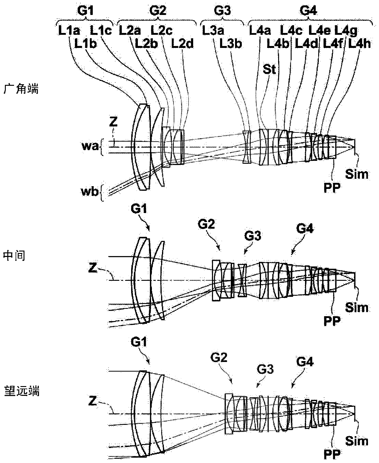
Embodiment 3

[0196] Example 3 Lens Data

[0197] face number radius of curvature face spacing nd vd 1 63.66603 1.6000 2.001 25.46 2 44.02708 8.5455 1.595 67.73 3 -366.67820 0.0100 4 41.66604 5.5001 1.497 81.61 5 128.13582 DD[5] 6 ∞ 0.8000 2.001 29.13 7 16.70874 4.0043 8 -60.43157 0.8100 1.613 44.27 9 18.98652 4.1364 2.104 17.02 10 -601.85497 0.7505 11 -56.29797 0.7501 2.104 17.02 12 ∞ DD[12] 13 -24.42216 0.7598 1.541 47.20 14 41.35198 1.5777 2.003 19.32 15 81.97129 DD[15] 16 -81.03389 3.0109 1.900 37.37 17 -22.38757 1.0000 18 (stop) ∞ 2.5000 19 25.00013 2.8689 1.497 81.61 20 110.96650 0.1000 21 18.38614 5.0002 1.538 74.70 22 -75.37886 0.9622 23 -26.86358 1.0000 1.923 18.90 24 86.79343 7.5002 25 -141.35753 3.0323 2.003 19.32 26 -23.67975 0.1000 ...


PUM


Abstract

The present invention provides a zoom lens having a small F value in the entire zoom range, and an imaging device including the zoom lens. From the object side, the positive first lens group (G1) that is fixed when changing magnification, the negative second lens group (G2) that moves when changing magnification, and the third negative lens group (G3) that moves when changing magnification And the fixed positive fourth lens group (G4) when zooming, the first lens group (G1) is composed of negative meniscus-shaped 1a lens (L1a), positive 1b lens (L1b) and positive 1c lens The second lens group (G2) consists of a negative 2a lens (L2a), a biconcave 2b lens (L2b), a positive 2c lens (L2c) and a negative 2d lens (L2d ), the third lens group (G3) is composed of a negative 3a lens (L3a) and a positive 3b lens (L3b), and the fourth lens group (G4) has a positive meniscus shape successively from the most object side 4a lens (L4a), aperture stop (St) and positive 4b lens (L4b).

Description

technical field [0001] The present invention relates to a zoom lens used in electronic cameras such as a digital camera, a video camera, a projection camera, and a surveillance camera, and an imaging device including the zoom lens. Background technique [0002] The zoom lens used in electronic cameras such as digital cameras, video cameras, projection cameras, and surveillance cameras consists of a first lens group with positive refractive power, a second lens group with negative refractive power, and a second lens group with negative refractive power. Three lens groups and the fourth lens group with positive refractive power are composed, and the first lens group and the fourth lens group are fixed relative to the image plane when zooming, so that both the zoom ratio and the zoom ratio can be achieved with a relatively simple structure. Miniaturization, so such a structure is often used. As a zoom lens having such a configuration, the zoom lens of Patent Document 1 is prop...

Claims


Application Information

Patent Timeline
Patent Type & Authority Patents(China)
IPC IPC(8): G02B15/17
CPCG02B15/17G02B15/20G02B15/144109G02B27/0025G02B3/04G02B5/005G02B9/00G02B9/34G02B9/60G02B13/0045G02B13/006G02B13/009G02B13/18G02B15/15G02B15/16G02B15/22
Inventor 犬饲孟长伦生
Owner FUJIFILM CORP
Why Eureka
Try Eureka