

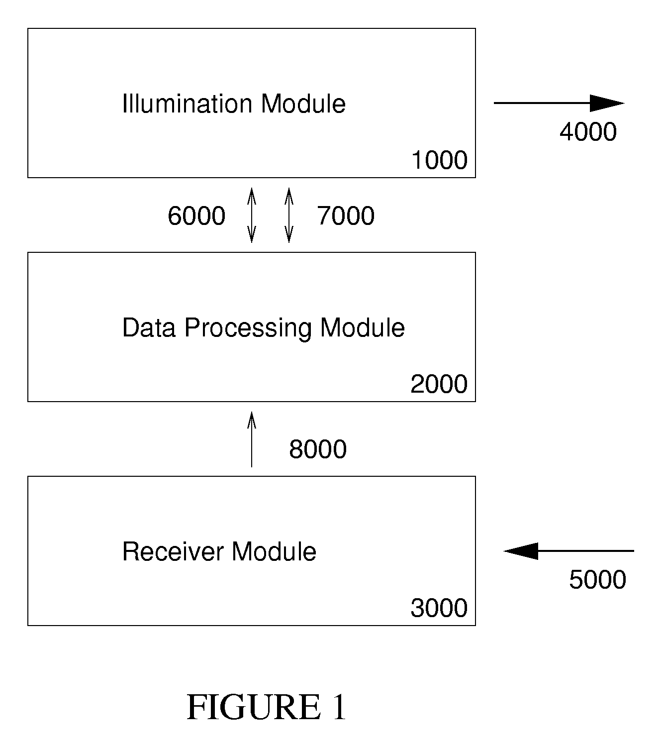
Multiplexed, spatially encoded illumination system for determining imaging and range estimation
a spatial encoded illumination and imaging technology, applied in the field of multi-dimensional spatial encoded illumination systems for determining imaging and range estimation, can solve the problems of difficult data processing task of fully automated correlation of all elements through-out the scene, difficult data processing task, and difficult implementation of digital range-finder devices, etc., to achieve greater complexity and diversity, and the effect of high intensities
- Summary
- Abstract
- Description
- Claims
- Application Information
AI Technical Summary
Benefits of technology
Problems solved by technology
Method used
Image

Examples
Embodiment Construction
Fundamental Operation
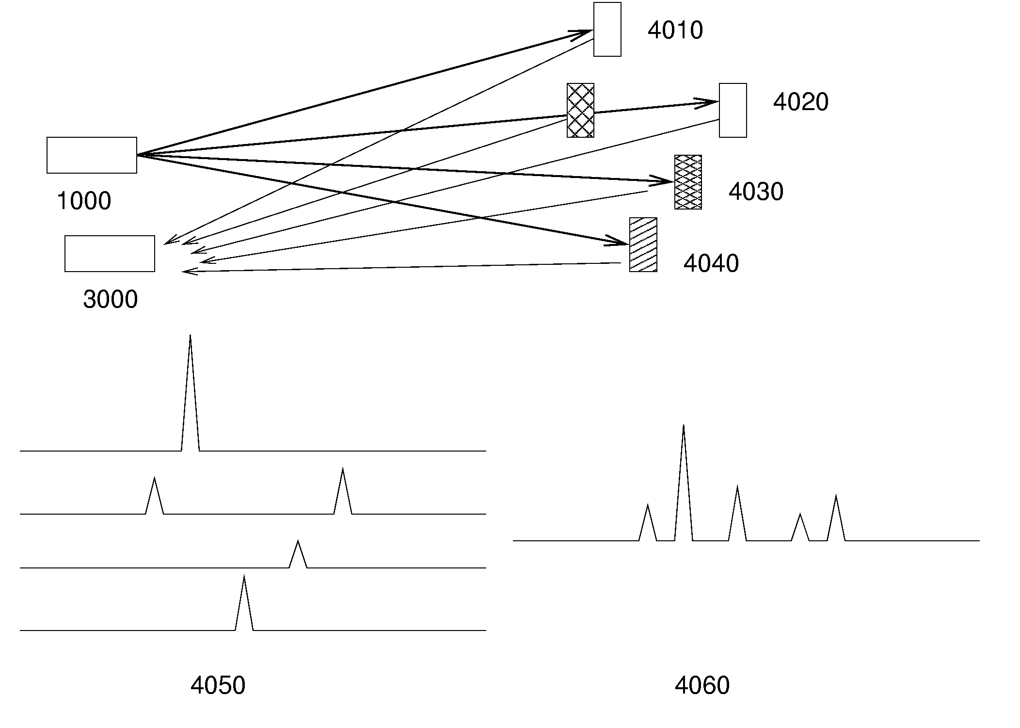
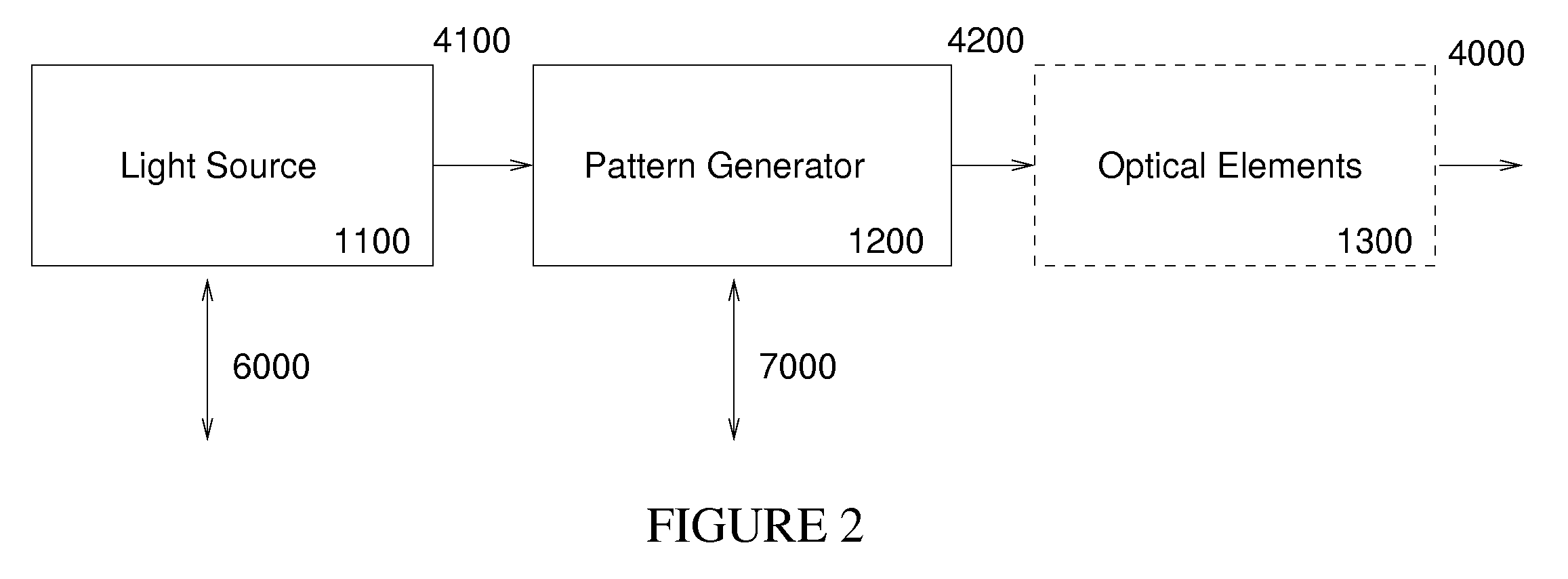
[0047] In order that we may distinguish the spatially encoded light intensity patterns that illuminate the object from the patterns on the physical structure that are used to manipulate the light beam waveform, we will refer to these respectively as the illumination patterns and the generating patterns. A simple example of illumination patterns shown in FIG. 6 parts 1010 through 1040 will be discussed later. The form of the generating patterns will depend on the manner in which the light is manipulated and, in general, may bear no resemblance to the illumination pattern.
[0048] The key features of this invention are:
[0049] (a) Assembling a pulsed light source (which can be accomplished using commercially available systems).
[0050] (b) Assembling a high-speed photo-detector and A / D signal sampling system (which can be accomplished using commercially available equipment).
[0051] (c) Choosing and designing the generating patterns corresponding to the illumination patt...
PUM
 Abstract
Description
Claims
Application Information