
A tdiccd image motion detection and compensation method

A compensation method and a technology of motion detection, applied in the field of aerospace remote sensing, can solve the problems of high cost and achieve the effect of improving image quality and improving image quality degradation

Active Publication Date: 2019-03-12
BEIJING RES INST OF SPATIAL MECHANICAL & ELECTRICAL TECH
View PDF4 Cites 0 Cited by
  • Summary
  • Abstract
  • Description
  • Claims
  • Application Information

AI Technical Summary

Problems solved by technology

At present, most of the mechanical image motion compensation methods and optical image motion compensation methods are used, and these methods are relatively expensive

Method used


Image

  • A tdiccd image motion detection and compensation method
  • A tdiccd image motion detection and compensation method
  • A tdiccd image motion detection and compensation method

Examples


Embodiment Construction

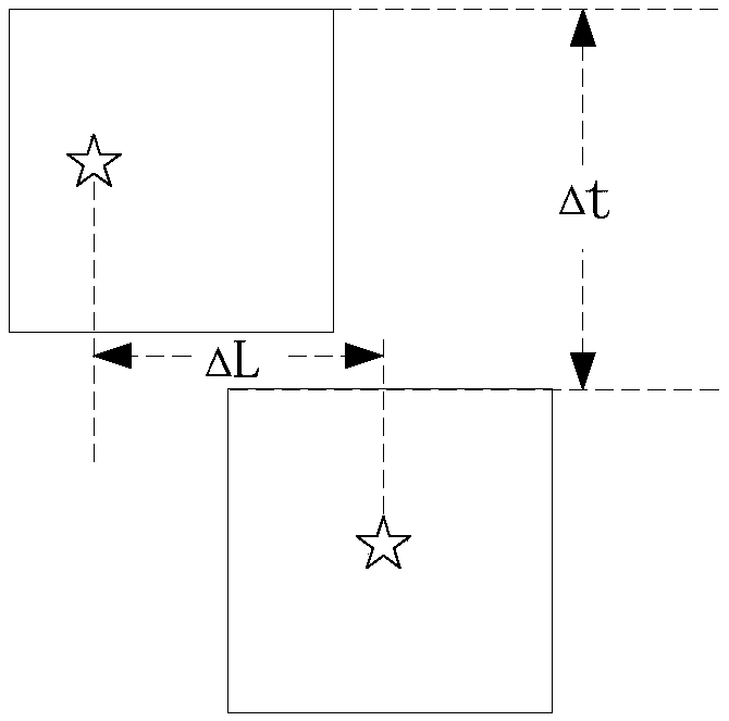
[0019] The invention relates to a TDICCD image motion detection and compensation method. The basic principle of image motion speed calculation is to image the same ground object in a short time to obtain two area array images. According to the imaging time interval and image motion distance, the image motion can be obtained. Moving speed, thus using the formula (1) (2) (3) can calculate the integration time of TDICCD.

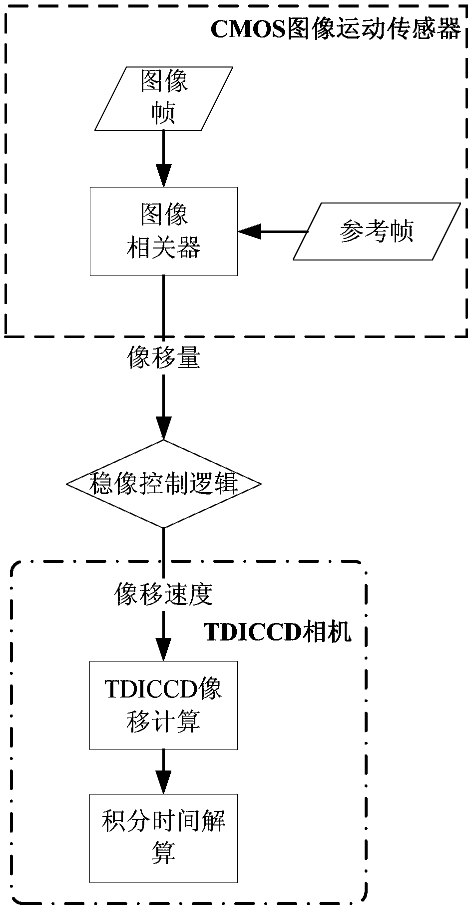
[0020] The specific implementation steps of the present invention are as follows image 3 As shown, the process is as follows:

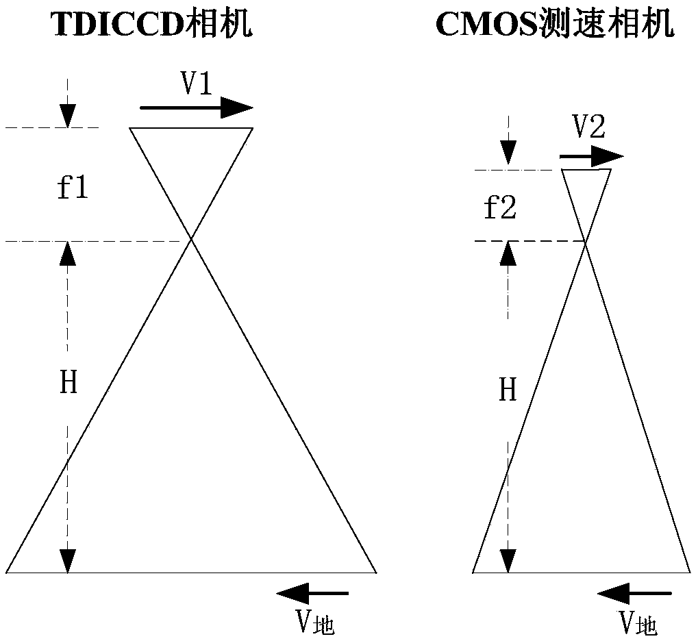
[0021] figure 1 The satellite system shown is equipped with a TDICCD camera and a CMOS camera respectively, assuming that the altitude of the satellite is H, and the focal length of the TDICCD camera is f 1 , the image moving speed is V 1 ; The focal length f of the CMOS camera 2 , the image moving speed is V 2 . The object running speed is V 地 , for two cameras installed on the same platform, the moving speed of ground object...


PUM


Abstract

The present invention relates to a TDICCD image motion detection and compensation method which is different from mechanical image motion compensation and laser ranging image motion compensation schemes, in load configuration of unknown elevation remote sensing detection, only a CMOS small camera and a proper amount of computing resources are added for real-time detection of image motion velocity of a ground object at an unknown elevation in a TDICCD focal plane, a given algorithm is used for real-time calculation of integral time Tint, image motion compensation is realized, and image quality degradation due to image motion can be improved to some extent. In deep space exploration missions, and because elevation information of a planet to be detected is unknown, a traditional calculation method is not feasible for integral time acquisition. The image motion compensation is realized by use of a CMOS + TDICCD dual camera model, the TDICCD image motion detection and compensation method is realizable on the planet, and original image quality can be effectively improved.

Description

technical field [0001] The invention relates to a TDICCD image motion detection and compensation method, which belongs to the technical field of aerospace remote sensing. Background technique [0002] The integration time of the TDICCD must match the speed of image movement in the focal plane. The mismatch between the two will cause image motion. The existence of image motion will lead to problems such as image blur, gray scale distortion, contrast and resolution reduction, which greatly affects the quality of imaging, and then makes it difficult to identify or extract the target. Therefore, it is necessary to It performs image motion compensation. [0003] There are many reasons for the image motion of the space optics TDICCD camera. At present, it is mainly aimed at the compensation of the forward image motion caused by the forward flight of the aircraft. At present, most of the mechanical image motion compensation methods and optical image motion compensation methods ar...

Claims


Application Information

Patent Timeline
Patent Type & Authority Patents(China)
IPC IPC(8): G01C11/02
CPCG01C11/02
Inventor 王旭明黄伟于生全王媛媛林悦贺玮魏志勇张孝弘
Owner BEIJING RES INST OF SPATIAL MECHANICAL & ELECTRICAL TECH
Learn More