Light momentum-excited nano beam microparticle mass measuring device and method

A quality measurement and nano-beam technology, which is applied in the field of nano-micro quality detection, can solve problems such as redundant noise, reduce measurement accuracy, and restrict measurement work, and achieve the effect of high measurement sensitivity and less measurement interference factors

Inactive Publication Date: 2017-03-22
SHANDONG UNIV OF TECH
View PDF4 Cites 11 Cited by
  • Summary
  • Abstract
  • Description
  • Claims
  • Application Information

AI Technical Summary

Problems solved by technology

In order to achieve higher mechanical sensitivity, it is necessary to use smaller micro-vibrators. However, how to drive and detect the vibration of the micro-resonator has become one of the problems that restricts the improvement of the accuracy of measuring the mass of nano-particles.
Based on the basic principles of quantum mechanics, in the process of driving and measuring, the driving and measuring equipment will cause disturbance and damage to the measured object, introduce unnecessary noise, and reduce the accuracy of measurement
In terms of vibration signal extraction of nano-micro resonators, the method of detecting displacement signals is usually used to convert displacement signals into optical, electrical, magnetic and other signals. By measuring these signals, high-sensitivity displacement measurement can be realized. The size and geometry of mechanical vibrators have strict requirements, and it is difficult to apply to the measurement of nanometer and sub-nanometer scale mechanical vibrators, potentially restricting the measurement of high-precision quality

Method used


Image

  • Light momentum-excited nano beam microparticle mass measuring device and method
  • Light momentum-excited nano beam microparticle mass measuring device and method
  • Light momentum-excited nano beam microparticle mass measuring device and method

Examples


example 1

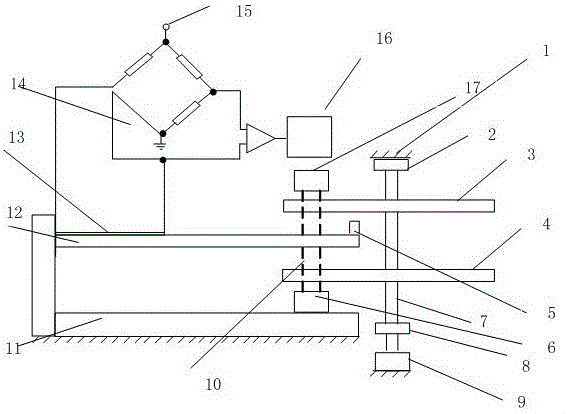
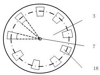
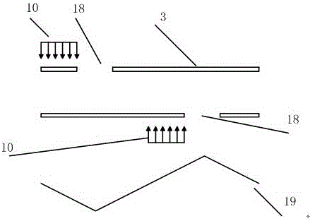
[0029] Example 1: Monochromatic light is vertically irradiated on the upper surface of the nanobeam 12, and the power P of the incident light passing through the light hole 18 is 1×10 -6 w, the force efficiency α of the incident light is 0.8, the refractive index n of the surrounding medium is 1, and the light speed c is 3×10 8 m / s, the number k of light holes on the disc is 1256, and the linear density of nanobeams 12 is 9.32×10 -9 kg / m, the elastic modulus E of the nano-beam 12 is 170GPa, the length l of the nano-beam 12 is 40 μm, the width b of the nano-beam 12 is 5 μm, and the height h of the nano-beam 12 is 0.8 μm. The magnitude of the light momentum excitation force generated by the light radiation passing through the light hole 18 is 2.0×10⁻³ nN.

[0030] When the nanobeam 12 resonates, it is measured that the rotation speed of the disk is 1700 revolutions per second, and the mass of the nanoparticle 5 is 2.7358×10 -15 kg.


PUM

PropertyMeasurementUnit
electrical resistanceaaaaaaaaaa
linear densityaaaaaaaaaa
elastic modulusaaaaaaaaaa

Abstract

The invention provides a light momentum-excited nano beam microparticle mass measuring device which comprises a sine-like light momentum excitation generation device and a micro mass detection device; monochromatic lights of an upper laser and a lower laser respectively irradiate light transmission holes of an upper disc and a lower disc; a driving motor drives a shaft to rotate, sine-like distribution light momentum excitation can be produced, and then a nano beam is excited to vibrate; the nano beam produces forced vibration under the action of alternating light momentum excitation, and resistance value of a resistor layer pasted at the root of the nano beam is changed; the signal can be output by utilizing a Wheatstone bridge circuit; and after amplification is carried out by virtue of a signal amplifier, spectral analysis can be carried out, vibration information images in a time domain and a frequency domain are obtained, and vibration parameters such as vibration amplitude and vibration frequency are obtained. Rotating speeds of the light momentum excitation generation device and the driving motor are changed, and light momentum excitation frequency is changed along with the rotating speeds; and when the nano beam resonates, an output current signal value is maximum, the resonant vibration frequency of the nano beam can be detected by measuring the voltage change peak, added mass adhered at the tail end of the nano beam is obtained by calculating, and thus the aim of measuring the mass of a nano-micro particle is achieved.

Description

technical field [0001] The patent of the present invention relates to a nano-micro mass detection device, in particular to a nano-micro mass measurement device, which belongs to the field of nano-micro mass detection. Background technique [0002] For mechanical resonators, nanomicrocantilevers are important devices for detecting weak force signals. In order to achieve higher mechanical sensitivity, it is necessary to use smaller micro-oscillators. However, how to drive and detect the vibration of the micro-resonator has become one of the problems that restricts the improvement of the accuracy of measuring the mass of nano-particles. Based on the basic principles of quantum mechanics, in the process of driving and measuring, the driving and measuring equipment will cause disturbance and damage to the measured object, introduce unnecessary noise, and reduce the accuracy of measurement. In terms of vibration signal extraction of nano-micro resonators, the method of detecting ...

Claims


Application Information

Patent Timeline
Patent Type & Authority Applications(China)
IPC IPC(8): G01N15/00G01N15/10
CPCG01N15/00G01N15/1031G01N2015/0038G01N2015/03G01N2015/1043
Inventor 刘灿昌刘文晓周长城马驰骋单越程相孟姜瑞瑞
Owner SHANDONG UNIV OF TECH
Why Eureka
Try Eureka