
A cable connection structure

A technology of cable connection and plug connector, which is applied in the direction of conductive connection, connection, parts of connection devices, etc. It can solve problems such as cable drop and multiple cables cannot be laid at equal distances, so as to reduce labor intensity, enhance laying quality, creative unique effects

Inactive Publication Date: 2019-02-19
国网河南嵩县供电公司 +1
View PDF6 Cites 0 Cited by
  • Summary
  • Abstract
  • Description
  • Claims
  • Application Information

AI Technical Summary

Problems solved by technology

[0002] Cable is an important medium for power transmission. In order to be easy to carry and store, the outside of the traditional cable is generally a circular structure. During the laying process of the cable, it is often necessary to connect multiple cables together before laying. The method of connecting cables as a whole is generally realized by using clamps. When using clamps to connect cables, clamps are set at intervals outside multiple cables to effectively connect the cables to each other. However, since the clamps are spaced Therefore, where there is no clamp, there will be unfavorable situations such as cable drop due to thermal expansion and contraction of the cable, and multiple cables cannot be laid equidistantly

Method used


Image

  • A cable connection structure
  • A cable connection structure

Examples


Embodiment Construction

[0014] The present invention can be explained in more detail through the following examples. The present invention is not limited to the following examples. The purpose of disclosing the present invention is to protect all changes and improvements within the scope of the present invention;

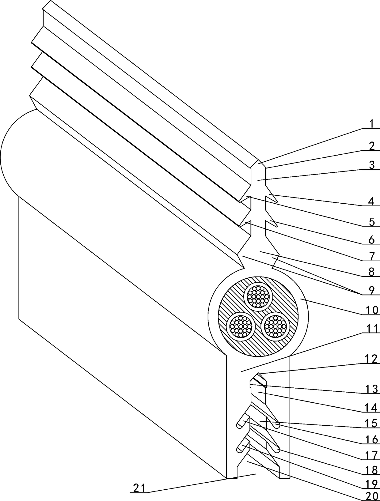
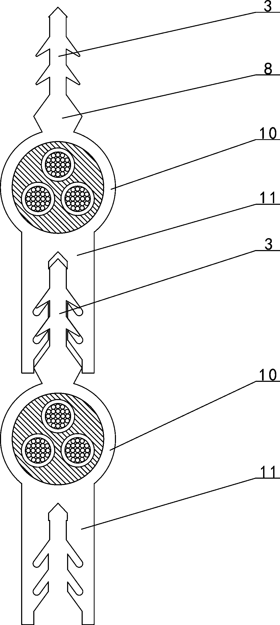
[0015] Such as figure 1 , 2 As shown, the cable connection structure, which is made of elastic material, includes an insert block and a clamping block 11, which are symmetrically arranged on both sides of the cable body 10, and the insert block includes a plug rod 3 and a base 8. , The base 8 is fixed on the cable, the lower end of the plunger 3 is connected with the upper end of the base 8, the upper end of the plunger 3 is provided with a plug connector 1, and the connecting transition part of the plug connector 1 and the plunger 3 is provided with convex strips symmetrically on both sides 2. A convex group A and a convex group B are symmetrically arranged on both sides of the plunger 3. The...


PUM


Abstract

The invention discloses a cable connection structure which comprises an insertion block and a clamp block (11). The insertion block and the clamp block are arranged symmetrically on both sides of a cable body (10). A raised group A and a raised group B are arranged symmetrically on both sides of an insertion rod (3). An insertion groove is arranged in the lower end of the clamp block (11). A first stop groove (16) which extends obliquely downward is arranged on one side of the transition of the lower end of a groove body A (14) and the upper end of a groove body B (15). A third stop groove (18) which extends obliquely downward is arranged on one side of the groove body B (15). A fourth stop groove (19) which extends obliquely downward is arranged on the other side of the groove body B (15). The lower end of the groove body B (15) is connected with a notch (21). According to the invention, the insertion block and the insertion groove are interconnected to realize cable connection, wherein the insertion block and the insertion groove are arranged at the relative positions of cables.

Description

Technical field [0001] The present invention relates to a cable, in particular to a cable connection structure. Background technique [0002] Cables are an important medium for power transmission. In order to facilitate carrying and storage, traditional cables generally have a circular structure outside. In the process of laying cables, it is often necessary to connect multiple cables together and then lay them. The method of connecting cables as a whole is generally realized by using clamps. When using clamps to connect cables, clamps are arranged at intervals outside the multiple cables to effectively connect the cables to each other. However, because the clamps are separated Therefore, where there is no clamp, the cable will fall due to thermal expansion and contraction of the cable, and the cables cannot be installed at equal distances. Summary of the invention [0003] In order to overcome the above-mentioned defects in the prior art, the present invention discloses a cable ...

Claims


Application Information

Patent Timeline
Patent Type & Authority Patents(China)
IPC IPC(8): H01R11/11H01R9/16H01R13/514
CPCH01R9/16H01R11/11H01R13/514
Inventor 党翠芳党艺飞
Owner 国网河南嵩县供电公司
Learn More