Back cover plate equipped with locking mechanism for railway train communication equipment, and use method for back cover plate

A technology of train communication and locking mechanism, which is applied in the direction of electrical equipment casing/cabinet/drawer, casing/cabinet/drawer parts, electrical components, etc. Problems such as the number of plates and structural parts, etc., to achieve the effect of satisfying the reliability of use, and the convenience and speed of installation or disassembly

Inactive Publication Date: 2017-03-22
TIANJIN 712 COMM & BROADCASTING CO LTD
View PDF5 Cites 2 Cited by
  • Summary
  • Abstract
  • Description
  • Claims
  • Application Information

AI Technical Summary

Problems solved by technology

[0002] In the field of railway train communication equipment, the fixed installation of some equipment needs to be close to the inner wall of the carriage, and the internal space of the equipment is limited. If the screw column is processed from the position of the front shell corresponding to the fixing hole of the rear cover plate, it will bring great harm to the design of the circuit board. great difficulty, and even bring about the problem of increasing the number of circuit boards and structural parts, thereby increasing the cost of the equipment
[0003] The design of the push-pull rear cover locking mechanism solves the problems of overly complex design, many structural parts, and difficult assembly in similar products.

Method used


Image

  • Back cover plate equipped with locking mechanism for railway train communication equipment, and use method for back cover plate
  • Back cover plate equipped with locking mechanism for railway train communication equipment, and use method for back cover plate
  • Back cover plate equipped with locking mechanism for railway train communication equipment, and use method for back cover plate

Examples


Embodiment Construction

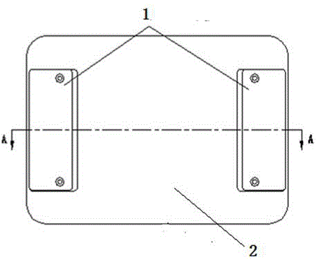
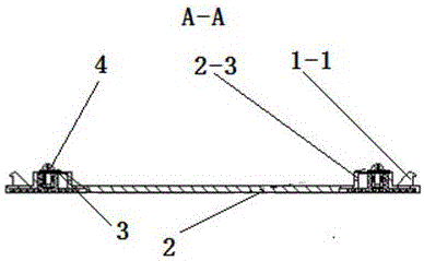
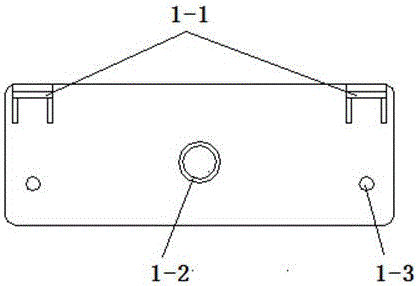
[0014] like Figure 1~7 As shown, buckle 1 is an injection molded part, and the material is engineering plastics. There are hooks 1-1, internal threaded columns 1-2, fixing holes 1-3, and rear cover plate 2 on the buckle 1, which are matched with the front shell of the equipment. It is a machine-added part, made of aluminum alloy, with two grooves 2-1 that match the buckle 1, four hook holes 2-2, and two internal thread column oblong holes 2-3 with bosses. And four threaded holes 2-4, the anti-loosening gasket is machined, and the material is galvanized steel; two buckles 1 are placed on the groove 2-1 of the rear cover 2, and the four hooks 1 of the buckle 1 -1 is inserted into the four hook via holes 2-2 of the back cover 2, and two internally threaded columns 1-2 are inserted into the two internally threaded column oblong via holes 2-3, and the internally threaded columns 1-2 are higher than the back cover The surface of the plate 2 is 0.15 mm, and the two screws 4 are eac...


PUM


Abstract

The invention relates to a back cover plate equipped with a locking mechanism for railway train communication equipment, and a use method for the back cover plate. The back cover plate comprises buckles, a back cover board, anti-releasing spacers and screws, wherein the two buckles are arranged on a groove of the back cover plate; four hooks of the buckles are inserted in four hook via holes of the back cover plate; two inner screw thread columns are inserted in two inner screw thread column long-circular via holes; the inner screw thread columns are 0.14-0.16mm higher than the surface of the back cover plate; and the two screws are sleeved with corresponding anti-releasing spacers and screwed in the two inner screw thread columns respectively, so that the buckles are not fallen off easily and can be slidable in the groove. By sliding the buckles, the four hooks can be hooked on the corresponding structure of the equipment shell; standard sunk screws are adopted to pass through four fixing holes of the buckles to be locked with four screw holes of the back cover plate tightly, so as to fix the buckles on the back cover plate; and the back cover plate has the beneficial effects of saving equipment cost, higher convenience and quickness in installing or detaching, capability of satisfying requirement of use reliability, and is mainly used for installation of the back cover plate of the equipment tightly attached to a compartment in the railway train communication equipment.

Description

technical field [0001] The invention relates to a railway train communication device, in particular to a rear cover plate with a locking mechanism for the railway train communication device. Background technique [0002] In the field of railway train communication equipment, the fixed installation of some equipment needs to be close to the inner wall of the carriage, and the internal space of the equipment is limited. If the screw column is processed from the position of the front shell corresponding to the fixing hole of the rear cover plate, it will bring great harm to the design of the circuit board. It is a big difficulty, and even brings about the problem of increasing the number of circuit boards and structural parts, thereby increasing the cost of the equipment. [0003] The design of the push-pull rear cover locking mechanism solves the problems of overly complex design, many structural parts, and difficult assembly in similar products. Contents of the invention ...

Claims


Application Information

Patent Timeline
Patent Type & Authority Applications(China)
IPC IPC(8): H05K5/02
CPCH05K5/0204
Inventor 宋勇王朋刘岩李学冲王芸刘小梅
Owner TIANJIN 712 COMM & BROADCASTING CO LTD
Why Eureka
Try Eureka