
Suspension device provided with damping steel rope and mounting method of suspension device

A suspension device and damping steel technology, applied to building components, walls, buildings, etc., can solve the problems of difficult construction and installation, difficulty in bearing heavy hanging curtains, etc., and achieve high construction efficiency, simple and fast installation, and safe and reliable use Effect

Pending Publication Date: 2017-11-10
YUNNAN CONSTR ENG GENERAL CONTRACTING
View PDF10 Cites 2 Cited by
  • Summary
  • Abstract
  • Description
  • Claims
  • Application Information

AI Technical Summary

Problems solved by technology

[0003] In order to solve the problem that the existing steel cable suspension device is difficult to bear the heavy weight of the hanging curtain, and the construction and installation are difficult, the present invention provides a method that can be pre-processed in the factory and assembled on the construction site, which is easy to operate, fast to install, safe in construction, and reliable. Reliable suspension device with damping steel cable for bearing heavy objects and installation method thereof

Method used


Image

  • Suspension device provided with damping steel rope and mounting method of suspension device
  • Suspension device provided with damping steel rope and mounting method of suspension device
  • Suspension device provided with damping steel rope and mounting method of suspension device

Examples


Embodiment Construction

[0021] Below in conjunction with accompanying drawing, the present invention is described in further detail:

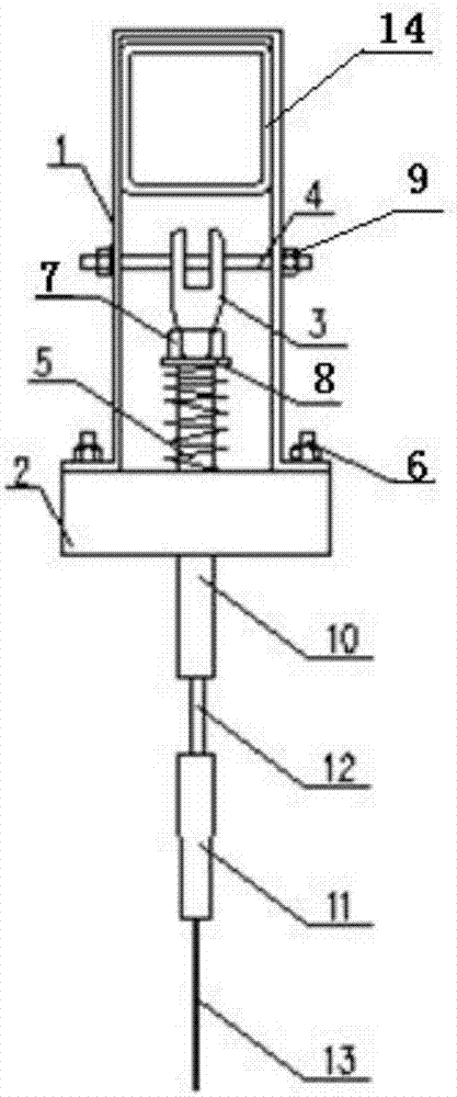
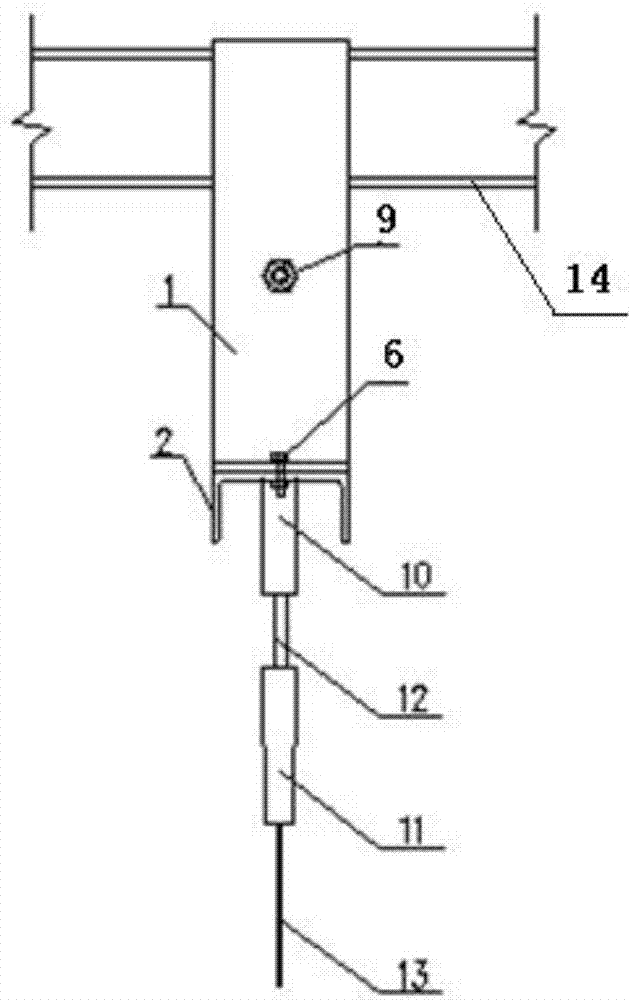
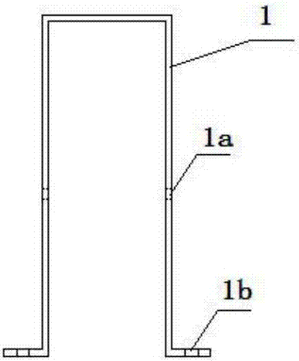
[0022] like figure 1 , figure 2 The suspension device with a damping cable shown includes a U-shaped hanging ring 1 with an opening facing downwards and hanging ears on both sides of the bottom end, a groove-shaped base 2 connected to the bottom of the hanging ring with the opening facing downwards, and crossing the hanging ring 1 The suspender 4 in the middle, the sling that is sleeved on the suspender 4, the sling passes through the base 2 and is connected with the hanging objects, and the upper part of the base 2 is set with a damper 5 on the sling. Set the direction of the U-shaped opening of the U-shaped hanging ring perpendicular to the direction of the notch of the groove-shaped base, and connect the lugs on both sides of the U-shaped hanging ring to the groove bottom of the groove-shaped base through bolts 6. The center is provided with a circular hole 2b f...


PUM


Abstract

The invention provides a suspension device provided with a damping steel rope and a mounting method of the suspension device. The suspension device comprises a U-shaped suspension loop (1) with a downward opening, a groove-shaped base (2) with a downward opening, a suspension rod (4) and a suspension cable, wherein a suspension lug is arranged on each of the two sides of the bottom end of the U-shaped suspension loop (1); the groove-shaped base (2) is connected with the bottom of the suspension loop; the suspension rod (4) transversely penetrates through the middle of the suspension loop; the suspension cable sleeves the suspension rod; the suspension cable penetrates through the base and is connected with a suspension object; a damper (5) sleeves the upper part of the base on the suspension cable; the direction of the U-shaped opening of the U-shaped suspension loop is perpendicular to the direction of the groove opening of the groove-shaped base, the suspension lugs arranged on the two sides of the U-shaped suspension loop are connected with the groove bottom of the groove-shaped base, and a round hole (2b), through which the suspension cable penetrates, is formed in the center of the groove bottom of the groove-shaped base. The device is heavy in suspension weight, safe and reliable in use, convenient in mounting and construction and high in construction efficiency.

Description

technical field [0001] The invention belongs to the technical field of construction engineering, and in particular relates to a steel cable suspension device under a stressed component of a building. Background technique [0002] In public buildings, personalized design and modern architectural decoration have led to a new form of architectural structure. Due to the decoration of building corridors and the functional requirements of building use, it is sometimes necessary to hang hanging curtains under the stressed components of the building or hang them in parts of the building. Hanging curtains meet individual design and functional requirements. Under normal circumstances, the use of cable suspension can solve the problem of hanging curtains, but for metal hanging curtains such as steel plates and aluminum alloys that exceed a certain weight, the existing steel cable suspension devices are difficult to bear the weight of the hanging curtains, and Construction and installa...

Claims


Application Information

Patent Timeline
IPC IPC(8): E04B9/00E04B2/88
CPCE04B2/88E04B9/006
Inventor 邓丽萍宁宏翔黄俊云罗成付欧阳文璟海类雄朱若愚冯丽云陈明青叶娇
Owner YUNNAN CONSTR ENG GENERAL CONTRACTING
Learn More