Magnetic mute lock body

A silent lock and magnetic technology, applied in the field of locks, can solve the problems of short service life, high installation position accuracy requirements, smooth transmission, and general stability.

Pending Publication Date: 2020-07-07
中山市雅丽斯五金制品有限公司
View PDF0 Cites 2 Cited by
  • Summary
  • Abstract
  • Description
  • Claims
  • Application Information

AI Technical Summary

Problems solved by technology

[0002] At present, the magnetic lock bodies widely used in the market all use the principle of magnetic attraction to make the lock tongue buckle into the buckle box, so that the lock tongue will not be exposed when the door is opened, and will not scratch the clothes or accidentally bruise. It adds a sense of beauty, so it will soon be favored by the majority of users, and the application will become more and more extensive. However, the existing silent lock body has exposed some problems. The structure of the existing silent lock body is traditional and old, and the structural design is cumbersome and complicated. The movement of the deadbolt assembly is not smooth enough, the fluency is low, the handle of the door handle is not smooth enough and comfortable, and the service life is short. Moreover, in the existing silent lock body, the installation position of the buckle box is fixed and cannot be adjusted flexibly. In this way, the accuracy of the installation position of the buckle box is high, the installation work is difficult, and the installation method of the buckle box magnet in the existing buckle box is relatively troublesome, and the assembly firmness of the buckle box magnet is average.
In addition, the transition of various states of the existing mute lock body and the smoothness and stability of the transmission between the components are average, and the collision sound of the components is loud when they are working, forming noise that affects people's rest, and the mute effect is not good.

Method used


Image

  • Magnetic mute lock body
  • Magnetic mute lock body
  • Magnetic mute lock body

Examples


Embodiment Construction

[0021] It should be understood that the specific embodiments described here are only used to explain the present invention, not to limit the present invention.

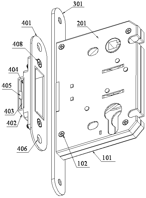
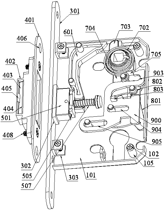
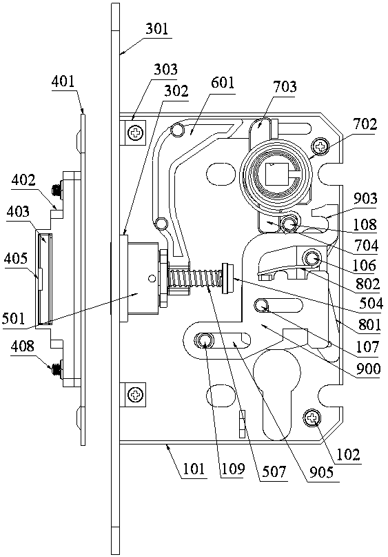
[0022] refer to Figure 1 to Figure 9 , an embodiment of a magnetic silent lock body of the present invention is proposed, including a base plate assembly installed in the door panel, a cover plate 201 covering the base plate assembly, and a lining plate located on the side of the base plate assembly and the cover plate 201 component, an adjustable buckle box component installed on the door frame and corresponding to the liner component, a deadbolt component installed on the bottom plate component, an L-shaped push button connected to the deadbolt component and capable of driving the deadbolt component to move laterally Slice 601, the peach dial component driven by the door handle to rotate and drive the push piece 601 to move laterally, the sliding piece assembly and lock piece 900 that plays the role of anti-locking...


PUM


Abstract

The invention discloses a magnetic mute lock body. The magnetic mute lock body comprises a bottom plate assembly installed in a door plate, a cover plate arranged on the bottom plate assembly in a covering mode, a lining plate assembly arranged on the side face of the bottom plate assembly and the side face of the cover plate, an adjustable buckling box assembly installed on a door frame and corresponding to the lining plate assembly, a spring bolt assembly installed on the bottom plate assembly, an L-shaped push piece connected with the spring bolt assembly and capable of driving the spring bolt assembly to transversely move, a shifting assembly driven by a door handle to rotate and driving the push piece to transversely move, a sliding piece assembly and a locking piece which play a counter locking role, and a lock cylinder playing a driving role on the sliding piece assembly, wherein the push piece, the shifting assembly, the sliding piece assembly and the locking piece are all installed on the bottom plate assembly.

Description

technical field [0001] The invention relates to the technical field of locks, in particular to a magnetic mute lock body. Background technique [0002] At present, the magnetic lock bodies widely used in the market all use the principle of magnetic attraction to make the lock tongue buckle into the buckle box, so that the lock tongue will not be exposed when the door is opened, and will not scratch the clothes or accidentally bruise. It adds a sense of beauty, so it will soon be favored by the majority of users, and the application will become more and more extensive. However, the existing silent lock body has exposed some problems. The structure of the existing silent lock body is traditional and old, and the structural design is cumbersome and complicated. The movement of the deadbolt assembly is not smooth enough, the fluency is low, the handle of the door handle is not smooth enough and comfortable, and the service life is short. Moreover, in the existing silent lock bod...

Claims


Application Information

Patent Timeline
Patent Type & Authority Applications(China)
IPC IPC(8): E05B47/00E05B17/00
CPCE05B17/0045E05B47/004
Inventor 任保收
Owner 中山市雅丽斯五金制品有限公司
Why Eureka
Try Eureka