
Temperature controllable type fermentation tank

A fermentation tank and tank body technology, applied in the field of temperature-controlled fermentation tanks, can solve the problems of inconvenient maintenance, limited output, easy aging, etc., and achieve the effects of increased volume, long service life, and easy control of fermentation quality.

Inactive Publication Date: 2017-04-05
CHONGQING ANTAO WINE IND
View PDF0 Cites 0 Cited by
  • Summary
  • Abstract
  • Description
  • Claims
  • Application Information

AI Technical Summary

Problems solved by technology

This fermenter is a typical vertical fermenter, and its fermentation output is greatly limited. In addition, its use in wine fermentation also has defects such as easy aging and inconvenient maintenance.

Method used


Image

  • Temperature controllable type fermentation tank

Examples


Embodiment Construction

[0013] The present invention will be further described below in conjunction with the accompanying drawings and specific embodiments, so that those skilled in the art can better understand the present invention and implement it, but the examples given are not intended to limit the present invention.

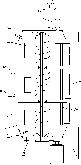
[0014] As shown in the figure, a temperature-controlled fermenter includes a tank body 1, the tank body is arranged horizontally, the upper part of the tank body is provided with a feeding port 2, and the lower part of the tank body is provided with a discharge port 3. A stirring device is also arranged on the tank body, and the stirring device includes a stirring shaft passing through the tank body in the axial direction, and a stirring blade is arranged on the stirring shaft, and the stirring blade is a spiral blade, and the filling body The outside of the pot is also provided with a power mechanism that drives the rotation of the stirring shaft, and the upper part of the pot is ...


PUM


Abstract

The invention discloses a temperature controllable type fermentation tank which includes a horizontal tank body. A material inlet is arranged on the upper part of the tank body and a material outlet is arranged on the lower part of the tank body. A stirring apparatus is disposed in the tank body and includes a stirring shaft that axially penetrates the tank body. Stirring blades are disposed on the stirring shaft and are spiral-type blades. A power mechanism driving the stirring shaft to rotate is disposed outside the tank body. A sampling pipe is disposed on the upper part of the tank body. A cooling apparatus is disposed in the tank body and includes a coil cooling pipe that is disposed in the tank body. An inlet and an outlet of the coil cooling pipe are all disposed on the bottom of the tank body. The fermentation tank has a horizontal structure, so that volume is greatly increased without influence on fermentation quality. Meanwhile, the fermentation tank is longer in service life and is easier to control in fermentation quality.

Description

technical field [0001] The invention relates to a fermenter, in particular to a temperature-controlled fermenter. Background technique [0002] Prior art 2014202079206 discloses a fermenter, which includes a tank body and a stirring device, the tank body is provided with a feed inlet and a discharge port, the stirring device includes a stirring motor, a stirring rod and a stirring paddle, and the stirring motor is located above the tank body One end of the stirring rod is connected to the stirring motor and the other end extends into the tank and is connected to the stirring paddle. The stirring paddle is arranged in a plate shape and provided with an interlayer. The cavity, the rod cavity is connected with the interlayer, the rod cavity is provided with wires, and one end of the stirring rod corresponding to the stirring motor is provided with a number of conductive rings, the conductive rings are electrically connected to the electric heating layer through the wires, and t...

Claims


Application Information

Patent Timeline
Patent Type & Authority Applications(China)
IPC IPC(8): C12M1/38C12M1/02
CPCC12M41/12C12M23/02C12M27/02
Inventor 王艺成
Owner CHONGQING ANTAO WINE IND
Learn More