Molar orthodontic appliance capable of conveniently applying orthodontic force
A technology of orthodontic force and appliance, applied in dentistry, orthodontics, prosthetics, etc., to achieve the effect of simple application, easy control, and reduction of the number of visits.
- Summary
- Abstract
- Description
- Claims
- Application Information
AI Technical Summary
Problems solved by technology
Method used
Image

Examples
Embodiment 1
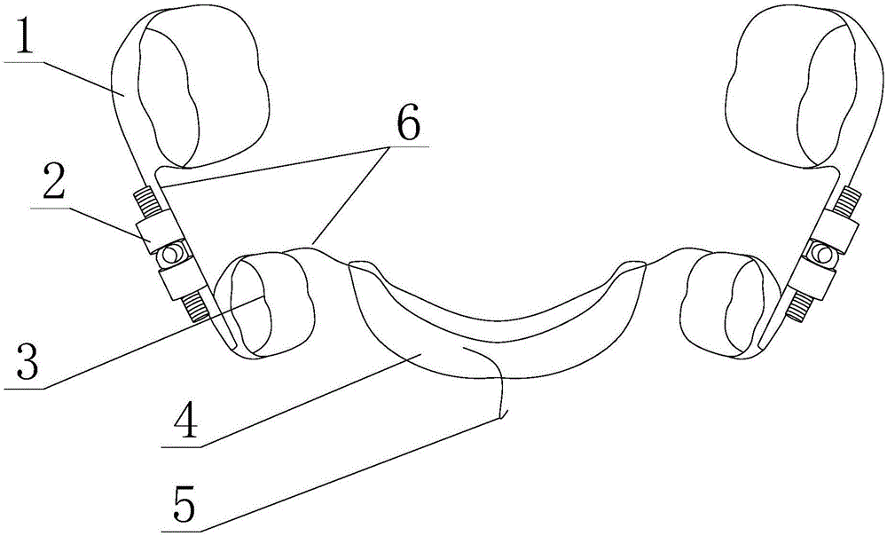
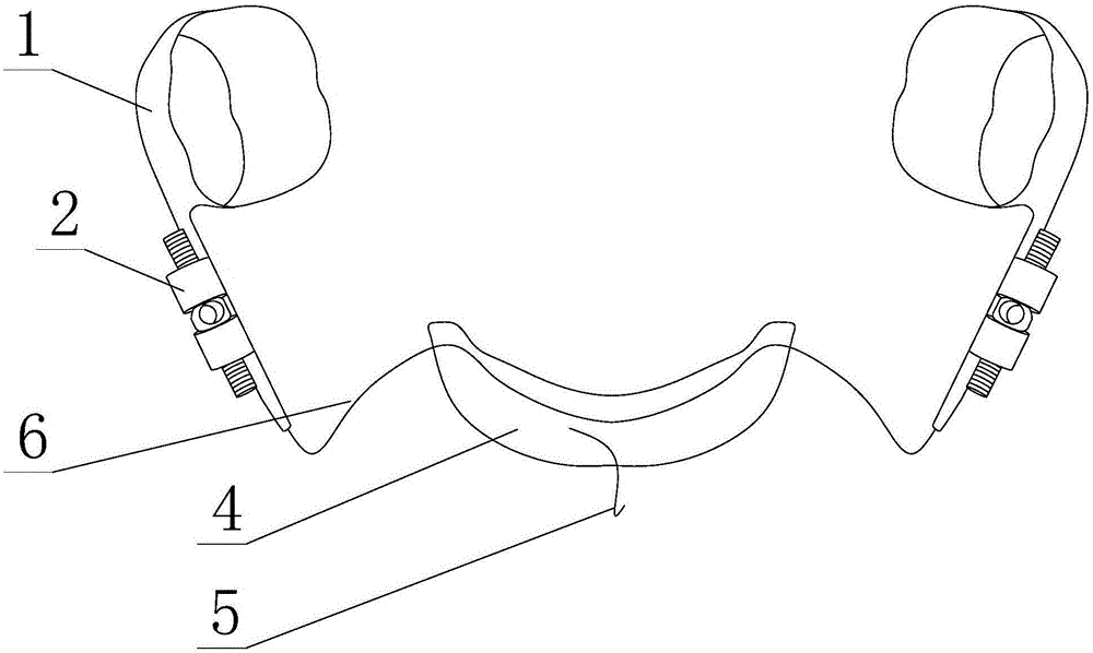
[0031] like Figure 1 to Figure 4 As shown, a molar appliance with convenient application of orthodontic force includes a first belt ring 1 and an anchorage, and also includes an expansion device connected in series between the first belt ring 1 and the anchorage;
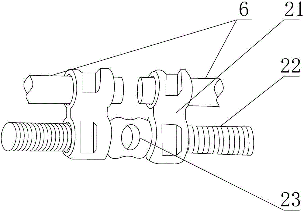
[0032] The expanding device includes a screw rod 22, and the screw rod 22 is provided with two sections of external thread, and the screw threads on the two sections of external thread are opposite in direction;
[0033] Nuts 21 are threadedly connected to each external thread segment, one of the nuts 21 is fixedly connected with the first belt ring 1, and the other nut 21 is fixedly connected with the anchorage;
[0034] The first belt ring 1 is used to be fixed on the molars to be treated, and the axial direction of the screw rod 22 is parallel to the distal direction of the molars.
[0035] Specifically, the anchorage refers to the structure used to resist the reaction force generated by the orthodontic force. ...
Embodiment 2
[0040] like Figure 1 to Figure 4 As shown, this embodiment is further limited on the basis of Embodiment 1: as the specific connection form between the expansion device and the first belt ring 1 and the anchorage, the two nuts 21 are connected to the first belt ring through different connecting arms 6 respectively. 1 and connected to the anchorage. Using the above method, after multiple times of correcting forces are applied to the molars, the connecting arms 6 on one or both sides of the expanding device can be plastically deformed to a certain extent through tools, so that the direction of the correcting force can be corrected. Simultaneously, in the existing position adjustment of the molars, the molars only need to move a few millimeters in the far or mesial direction. In this way, for the comfort of the patient, the total length of the screw rod 22 does not need to be too long. A few millimeters is enough, and the connecting arm 6 is used as the intermediate connecting ...
Embodiment 3
[0047] like Figure 1 to Figure 4 As shown, this embodiment provides a more detailed solution on the basis of Embodiment 1: in order to facilitate the application of torque to the screw 22 to make it rotate around its own axis and achieve the purpose of adjusting the relative position of the two nuts 21, the The screw 22 is also provided with a driving segment 23 , and the driving segment 23 is provided with a plurality of holes, and the holes are uniformly distributed in a circular shape relative to the axis of the screw 22 . In this solution, by setting multiple holes and limiting the relative positions of the multiple holes, the screw rod 22 can be rotated to any state, and the corresponding holes are exposed to the position that is convenient for the patient to insert the force-applying member, that is, this solution greatly The convenience of adjusting the appliance is improved.
[0048] Because when the patient adjusts the expansion device, it is difficult to avoid appl...
PUM
 Abstract
Description
Claims
Application Information
 - R&D
- Intellectual Property
- Life Sciences
- Materials
- Tech Scout
- Unparalleled Data Quality
- Higher Quality Content
- 60% Fewer Hallucinations
Browse by: Latest US Patents, China's latest patents, Technical Efficacy Thesaurus, Application Domain, Technology Topic, Popular Technical Reports.
© 2025 PatSnap. All rights reserved.Legal|Privacy policy|Modern Slavery Act Transparency Statement|Sitemap|About US| Contact US: help@patsnap.com