
Anti-interference method based on light source array rotation characteristic in visible light positioning

A light source array and rotation characteristic technology, applied in the field of navigation and positioning, can solve problems such as false light sources and adverse effects of the positioning process

Active Publication Date: 2017-04-26
DALIAN UNIV OF TECH
View PDF5 Cites 11 Cited by
  • Summary
  • Abstract
  • Description
  • Claims
  • Application Information

AI Technical Summary

Problems solved by technology

In the indoor environment, there are often glass windows, mirrors or smooth wall structures, which will reflect the image of the indoor light source and form a false light source, which will adversely affect the positioning process

Method used


Image

  • Anti-interference method based on light source array rotation characteristic in visible light positioning

Examples


Embodiment Construction

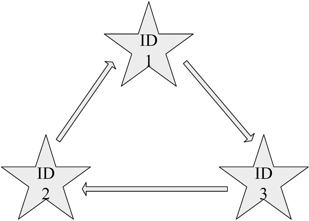
[0016] In the specific implementation process, the ID of each array element can be distinguished by the color of each array element in the dot matrix, the flicker frequency, the modulation information or the delay relationship between the array elements. The three array elements can be arranged in a triangle in a clockwise (or counterclockwise) order according to the ID to facilitate identification. The present invention includes following two processes:

[0017] The first step, the construction process

[0018] When installing a light source, a light source array is used instead of a point light source; the light source array includes 3 point light sources;) IDs are assigned to the 3 point light sources; and all point light sources are arranged into a polygonal lattice in a clockwise rotation order;

[0019] The second step, the positioning process

[0020] 2.1) The positioning terminal recognizes the light source array through the camera, and identifies the ID of each poin...


PUM


Abstract

The invention belongs to the technical field of indoor positioning, and provides an anti-interference method based on light source array rotation characteristic in visible light positioning. The method employs a light source array for substituting a single light source, the light source array is distributed according to a clockwise or anticlockwise rule in a circulation mode according to ID of each spot light source; while receiving, an arrangement sequence of the spot light source in the light source array is monitored for screening the true and false of the light source. when a receiver is positioned, the light source array identified by a camera is verified; if the spot light source rotation order of the imaging light source array conforms to the condition while installing, the spot light source is the reliable light source, so that the rotation order can be substituted into a resolving process; if not, the spot light source is the fake light source formed by reflection, and the rotation order cannot be substituted into the resolving process. The method has the beneficial effect that compared with a traditional visible light positioning technology by taking the spot light source as a base, the method can effectively distinguish the real light source from the fake light source caused by reflection.

Description

technical field [0001] The invention belongs to the technical field of navigation and positioning, and relates to indoor positioning, in particular to a visible light positioning method. Background technique [0002] In visible light positioning technology, indoor ceiling light sources are often used as references, and each light source is identified through the user receiver camera, or the user's position is estimated by fingerprint positioning means or geometric calculation methods. In the indoor environment, glass windows, mirrors or smooth wall structures often appear, which will reflect the image of the indoor light source and form a false light source, thereby adversely affecting the positioning process. Contents of the invention [0003] The technical problem to be solved by the present invention is that the reflected image of indoor reflective objects forms a false light source, which leads to positioning errors. The purpose of the present invention is to provide ...

Claims


Application Information

Patent Timeline
Patent Type & Authority Applications(China)
IPC IPC(8): G01C21/20
CPCG01C21/206
Inventor 邹德岳
Owner DALIAN UNIV OF TECH
Learn More