A photoelectric cursor relative position measuring device

A technology of relative position and measuring device, which is applied in the direction of measuring device, optical device, instrument, etc., can solve the problems of inability to guarantee the accuracy and large distance between the relative positions of electric markers.

Active Publication Date: 2022-05-03
PLA NO 63686 CORPS
View PDF5 Cites 0 Cited by
  • Summary
  • Abstract
  • Description
  • Claims
  • Application Information

AI Technical Summary

Problems solved by technology

For large-scale measurement and control antennas, the distance between the relative position of the cursor and the electric scale is relatively large. In the case of manual measurement and its inconvenience, and the accuracy cannot be guaranteed, there is an urgent need for a position measurement device to accurately measure it.

Method used


Image

  • A photoelectric cursor relative position measuring device
  • A photoelectric cursor relative position measuring device
  • A photoelectric cursor relative position measuring device

Examples


Embodiment Construction

[0020] The present invention will be described in further detail below in conjunction with the embodiments of the accompanying drawings.

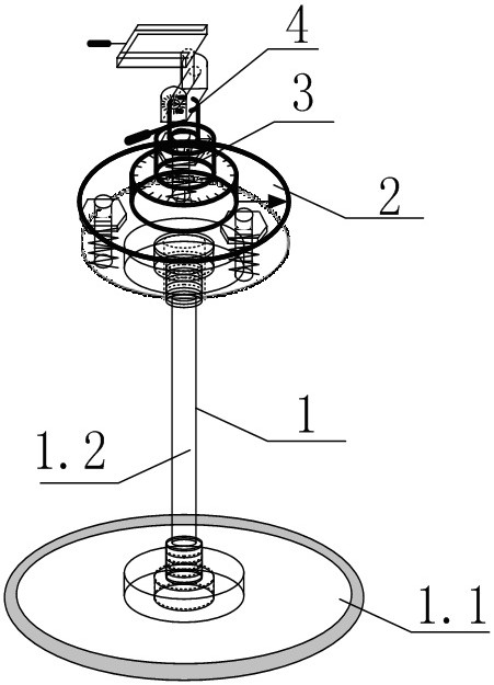
[0021] as Figure 1 As shown, the present invention relates to a photoelectric target relative position measurement apparatus, which comprises a bottom-up sequentially connected bench 1, platform 2, horizontal rotary body 3 and vertical rotor 4, wherein:

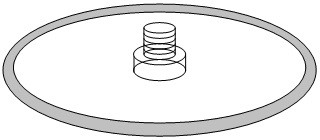
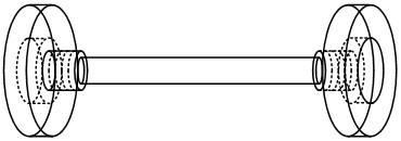
[0022] as Figure 2 —4, said bench 1 includes a chassis 1.1, a connecting rod 1.2, a tray 1.3 and a leveling bolt 1.4, the chassis 1.1 is a disc structure for supporting the entire device, there is a cylindrical structure in the center of its front, a cylindrical structure center is raised with a bolt for connecting with the connecting rod 1.2; the connecting rod 1.2 is a "barbell" cylindrical structure, the cylindrical ends of the cylinder are equipped with a "straw hat-shaped" structure, "straw hat-shaped" edge is a circular body, "straw hat-shaped" The cap is an inner spiral toroidal cylind...


PUM


Abstract

The invention relates to a device for measuring the relative position of a photoelectric scalar, which is composed of a stand, a platform, a horizontal swivel body and a vertical swivel body. The relative position measurement of the photoelectric scalar and the electric scalar is conveniently realized by using a projection method and through distance measurement and relative angle relationship. Place the device directly in front of the photoelectric mark, make the infrared port of the laser range finder perpendicular to the center of the transition rod, perform horizontal leveling through the leveling water column of the laser range finder, and turn the platform so that the platform marking line is perpendicular to the normal position of the photoelectric mark . Turn the horizontal and vertical swivels so that the laser rangefinder laser points to the center of the antenna, and get the distance value and the horizontal and vertical angle values; turn the horizontal and vertical swivels again so that the laser rangefinder laser points to the cursor, and get the distance value and horizontal and vertical angle values. The vertical angle value is calculated by the Pythagorean law to obtain the relative position of the photoelectric cursor. In application, the invention is convenient to place and adjust, can realize the measurement of the relative position of the target, and has extremely strong application value.

Description

Technical field [0001] The present invention relates to a photoelectric target relative position measurement device. It belongs to the field of mechanical engineering technology. Background [0002] The so-called electric axis is the communication antenna under a certain frequency of the pointing, because the shipboard each band of the measurement and control equipment radar axis is a virtual axis, can not be accurately calibrated, so the measurement and control antenna pitch arm side is equipped with glasses as a virtual axis, that is, the direction of the telescope represents the direction of the electric axis; the other side is equipped with a low-light television, requiring the optical axis of the low-light television to be parallel to the pointing of the telescope, that is, the pointing of the telescope, the optical axis of the low-light television is parallel to the axis, and the axis is in the center of both. Since the telescope is not convenient to participate in the tas...

Claims


Application Information

Patent Timeline
Patent Type & Authority Patents(China)
IPC IPC(8): G01B11/00
CPCG01B11/00
Inventor 潘高峰何剑伟毛南平谢勇刘四方梁盛夏利利
Owner PLA NO 63686 CORPS
Why Eureka
Try Eureka