Gray-scale signal compensation unit, gray-scale signal compensation method, source driver and display device

A technology of signal compensation and source driving, which is applied to instruments, static indicators, etc., can solve the problems of reduced charging speed, reduced brightness, and unreachability, and achieves the effect of equal charging rate and uniform display brightness

Active Publication Date: 2017-05-10
BEIJING BOE DISPLAY TECH CO LTD +1
View PDF7 Cites 42 Cited by
  • Summary
  • Abstract
  • Description
  • Claims
  • Application Information

AI Technical Summary

Problems solved by technology

figure 1 It is a schematic diagram of the source drive circuit in the prior art when providing grayscale signals to pixels located at different positions, such as figure 1 As shown, the solid line represents the waveform of the gray-scale signal loaded by the source drive circuit to the pixel closer to it, and the dotted line represents the waveform of the gray-scale signal loaded by the source drive circuit to the pixel farther away from it. When distant pixels provide grayscale signals, affected by RC Delay, the charging speed drops, and the target grayscale cannot be reached within the preset charging time, that is, the charging rate is insufficient
[0004] It can be seen from the above content that the charging rate of the pixels on the display panel decreases gradually from bottom to top, resulting in a gradual decrease in the brightness of the display panel from bottom to top, and the display panel displays uneven brightness.

Method used


Image

  • Gray-scale signal compensation unit, gray-scale signal compensation method, source driver and display device
  • Gray-scale signal compensation unit, gray-scale signal compensation method, source driver and display device
  • Gray-scale signal compensation unit, gray-scale signal compensation method, source driver and display device

Examples


Embodiment Construction

[0053] In order for those skilled in the art to better understand the technical solution of the present invention, a gray scale signal compensation unit, compensation method, source driver and display device provided by the present invention will be described in detail below with reference to the accompanying drawings.

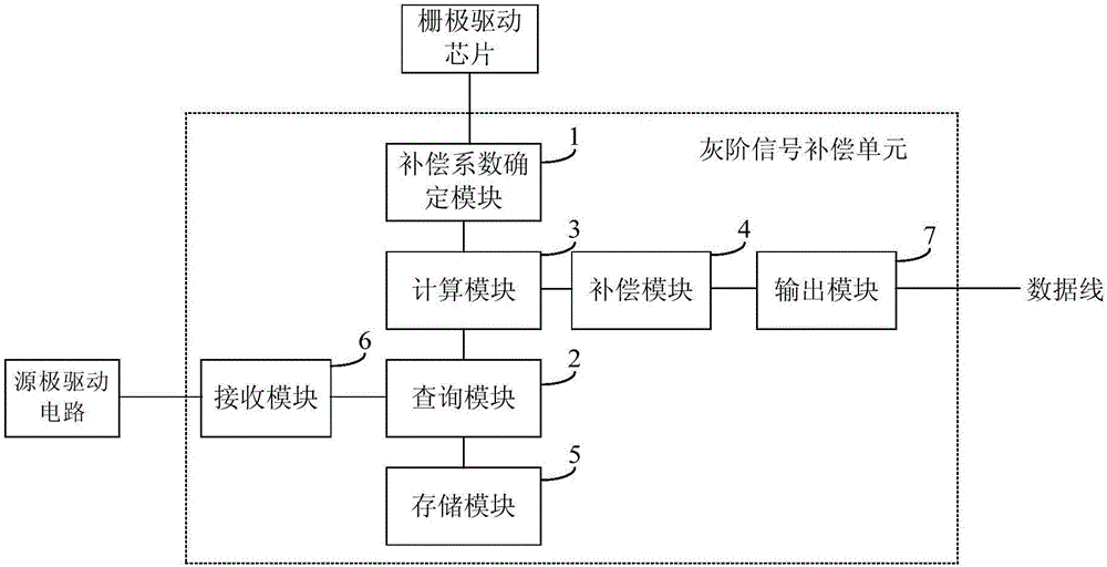
[0054] figure 2 A schematic structural diagram of a grayscale signal compensation unit provided in Embodiment 1 of the present invention, as shown in figure 2As shown, the gray-scale signal compensation unit is connected to the source drive circuit for compensating the initial gray-scale signal output by the source drive circuit. The gray-scale signal compensation unit includes: a compensation coefficient determination module 1, a query module 2, The calculation module 3 and the compensation module 4 are all connected to the query module 2 , the compensation coefficient determination module 1 and the compensation module 4 . Among them, the compensation coef...


PUM


Abstract

The invention discloses a gray-scale signal compensation unit, a gray-scale signal compensation method, a source driver and a display device. The gray-scale signal compensation unit comprises a compensation coefficient determining module, a query module, a computation module and a compensation module, wherein the compensation coefficient determining module is used for determining a compensation coefficient in accordance with location of a to-be-driven pixel; the query module is used for querying a reference compensation value corresponding to an initial gray-scale signal in accordance with a gray-scale compensation corresponding relation table of a row of pre-stored pixels which keep a farthest distance away from a source drive circuit; the computation module is used for computing an actual compensation value corresponding to the to-be-driven pixel in accordance with the compensation coefficient and the queried reference compensation value; and the compensation module is used for compensating the initial gray-scale signal in accordance with the actual compensation value. According to the technical scheme, the initial gray-scale signal, which is outputted from the source drive circuit, can be effectively compensated, so that the pixels in various rows of a display panel are equal in charging rate, and the display panel is uniform in display brightness.

Description

technical field [0001] The invention relates to the field of display technology, in particular to a grayscale signal compensation unit, a compensation method, a source driver and a display device. Background technique [0002] With the continuous development of display technology, display devices with large size, high resolution and high refresh rate have become a research hotspot in the field of display. [0003] In the existing display device, the source driving electrode is arranged on one side (generally the lower side) of the display panel. When the source driving electrode charges the pixel through the data line, along with the The greater the distance, the greater the resistance of the data line and the capacitance between the data line and the common electrode, that is, the more serious the resistance-capacitance delay (RC Delay). figure 1 It is a schematic diagram of the source drive circuit in the prior art when providing grayscale signals to pixels located at dif...

Claims


Application Information

Patent Timeline
Patent Type & Authority Applications(China)
IPC IPC(8): G09G3/36G09G3/3275
CPCG09G3/3275G09G3/3685G09G2320/0233G09G3/2011G09G2300/08G09G2310/0275G09G2320/0223G09G2320/0285G09G3/2007G09G2310/06G09G2320/029
Inventor 汪建明周留刚陈明王洁琼栗首张超朱昊
Owner BEIJING BOE DISPLAY TECH CO LTD
Why Eureka
Try Eureka