Display panel, manufacturing method thereof and display device

A technology of a display panel and a manufacturing method, which is applied to instruments, nonlinear optics, optics, etc., can solve the problems of uneven display brightness and affect the user's visual experience, and achieve the effect of uniform overall display brightness and improved visual experience.

Inactive Publication Date: 2018-10-19
SHANGHAI TIANMA MICRO ELECTRONICS CO LTD
View PDF6 Cites 8 Cited by
  • Summary
  • Abstract
  • Description
  • Claims
  • Application Information

AI Technical Summary

Problems solved by technology

During the bending process, because the display panel is subject to shear stress, the cell thickness of the display panel becomes thinner, so that the glass substrate of the display panel is no longer optically isotropic, but has birefringence, so that the linearly polarized light will pass through It becomes circularly polarized light, and in the case of bending, the brightness of the display panel is dimmed at the sudden change of curvature (the place where the thickness of the liquid crystal cell becomes thinner), forming dark lines, which leads to the phenomenon of uneven display brightness of the display panel in the pure color display state. Greatly affect the user's visual experience

Method used


Image

  • Display panel, manufacturing method thereof and display device
  • Display panel, manufacturing method thereof and display device
  • Display panel, manufacturing method thereof and display device

Examples


Embodiment Construction

[0036] Certain terms are used, for example, in the description and claims to refer to particular components. Those skilled in the art should understand that hardware manufacturers may use different terms to refer to the same component. The specification and claims do not use the difference in name as a way to distinguish components, but use the difference in function of components as a criterion for distinguishing. As mentioned throughout the specification and claims, "comprising" is an open term, so it should be interpreted as "including but not limited to". "Approximately" means that within an acceptable error range, those skilled in the art can solve the technical problem within a certain error range and basically achieve the technical effect. The subsequent description of the specification is a preferred implementation mode for implementing the application, but the description is for the purpose of illustrating the general principle of the application, and is not intended...


PUM


Abstract

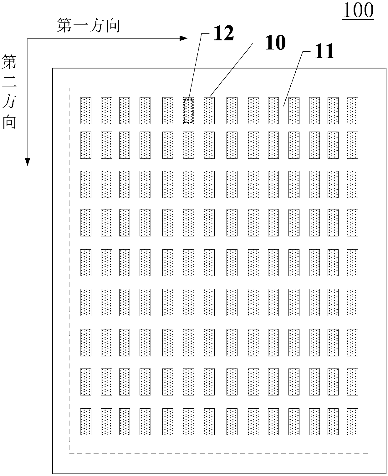
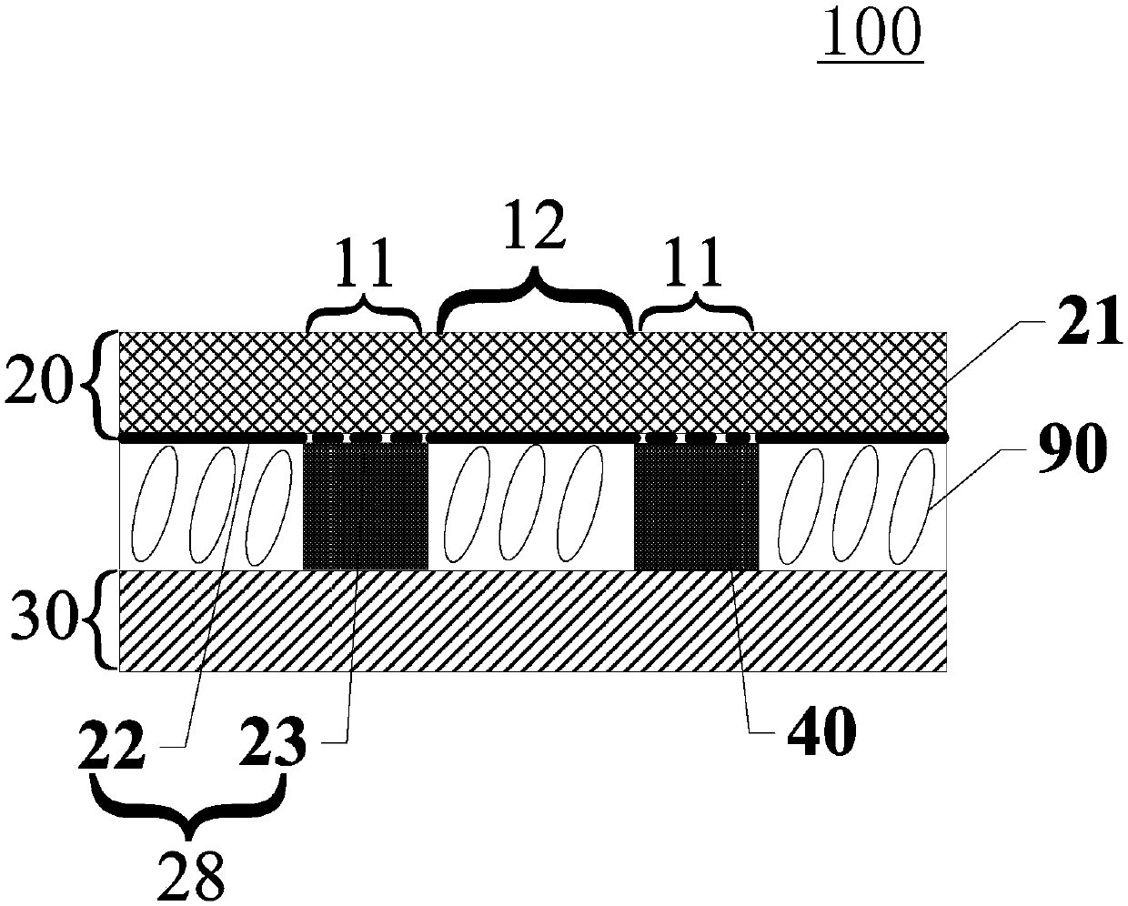
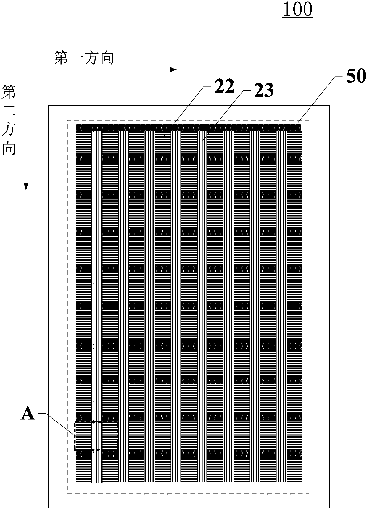
The invention discloses a display panel, a manufacturing method thereof and a display device, and relates to the technical field of displaying. The display panel comprises a first substrate and a second substrate which are opposite to each other and liquid crystals filling the portion between the first substrate and the second substrate, and high-molecular polymer stopping walls are further arranged between the first substrate and the second substrate; the first substrate comprises a first substrate body and a first metal wire grid which is arranged at the side, close to the second substrate,of the first substrate body, the first metal wire grate comprises a first main metal wire grate body and a first subsidiary metal wire grate body, and the extension direction of the first main metal wire grate body is perpendicular to that of the second subsidiary metal wire grate body; the orthographic projection of the first main metal wire grate body on a plane where the display panel is located overlaps with a light transmittance area, and the orthographic projection of the first subsidiary metal wire grate body on the plane where the display panel is located overlaps with the high-molecular polymer stopping walls. In this way, dark fringes are effectively prevented from being formed in the display process, and the user experience can be improved.

Description

technical field [0001] The present application relates to the field of display technology, in particular, to a display panel, a manufacturing method thereof, and a display device. Background technique [0002] In recent years, with the development of display panels, the existing technology proposes a curved display panel. The curved display panel can give users a better visual experience. The reason is that human eyeballs are convex and curved, and the curved display panel The radian can ensure that the distance between each position on the eyeball and the display panel is more equal, so as to bring a better sensory experience. In addition to the different visual experience, the curved display panel gives people a wider field of view, because the edge slightly curved towards the user can It is closer to the user and achieves basically the same viewing angle as the central position of the curved display panel. In addition to being a large-size display panel, the usage scenari...

Claims


Application Information

Patent Timeline
Patent Type & Authority Applications(China)
IPC IPC(8): G02F1/1335G02F1/1339G02F1/1333
CPCG02F1/1333G02F1/133528G02F1/13394G02F1/133548
Inventor 孔祥建高春梅
Owner SHANGHAI TIANMA MICRO ELECTRONICS CO LTD
Why Eureka
Try Eureka