Driving system for dynamic heat dissipation and layout in enclosure structure

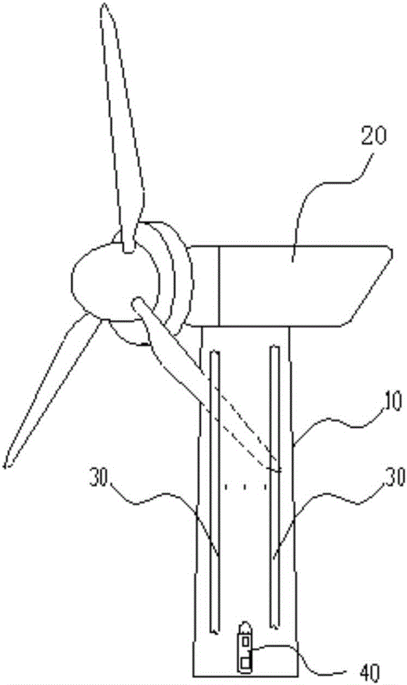
An enclosure structure and drive system technology, applied in the direction of engines, wind engines, machines/engines, etc., can solve the problems that the power transmission cable 30 is difficult to dissipate heat and affect the service life of the power transmission system, and achieve the effect of dynamic heat dissipation

Active Publication Date: 2017-05-10
BEIJING GOLDWIND SCI & CREATION WINDPOWER EQUIP CO LTD
View PDF5 Cites 6 Cited by
  • Summary
  • Abstract
  • Description
  • Claims
  • Application Information

AI Technical Summary

Problems solved by technology

[0011] That is to say, the temperature inside the tower is often at a high temperature, especially in summer. At this time, the high internal temperature makes it difficult for the power transmission cable 30 to dissipate heat, and the temperature is even higher, which affects its service life and the safety of the entire power transmission system.

Method used


Image

  • Driving system for dynamic heat dissipation and layout in enclosure structure
  • Driving system for dynamic heat dissipation and layout in enclosure structure
  • Driving system for dynamic heat dissipation and layout in enclosure structure

Examples


Embodiment Construction

[0090] In order to enable those skilled in the art to better understand the technical solutions of the present invention, the present invention will be further described in detail below in conjunction with the accompanying drawings and specific embodiments. For ease of understanding and succinct description, this article combines the dynamic heat dissipation method and dynamic heat dissipation system of the envelope structure and its internal heat sources for an overall description, and the beneficial effects will not be discussed repeatedly.

[0091] In the solution of the present invention, the dynamic heat dissipation method of the heat source inside the enclosure structure is as follows:

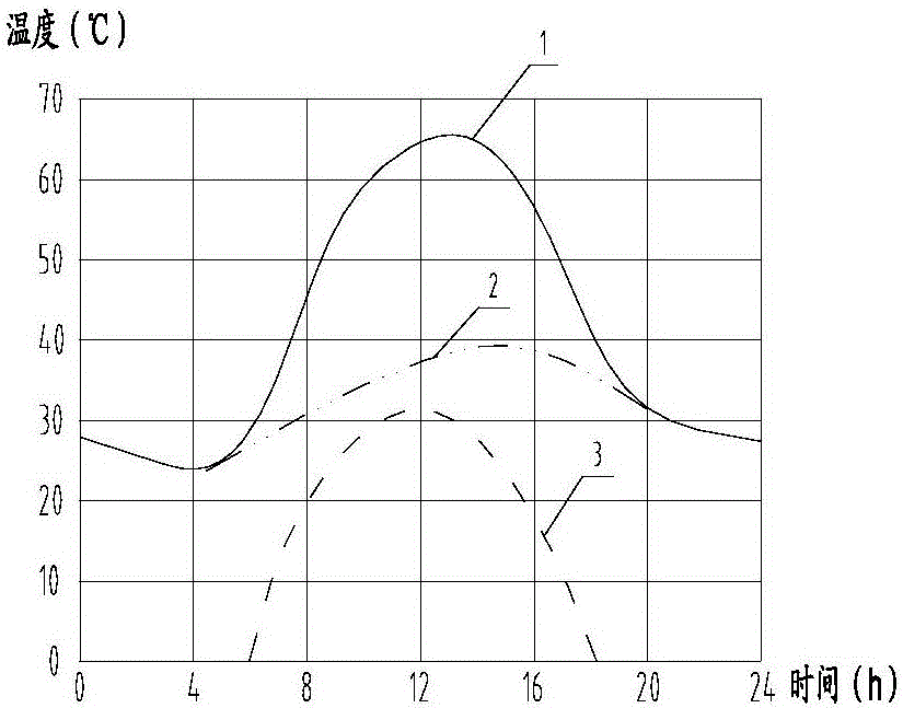
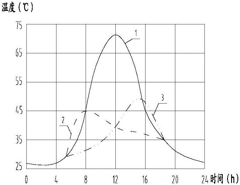
[0092] Obtain relatively low temperature areas of the envelope;

[0093] Driving the heat source to move to the relatively low temperature area.

[0094] The core of the present invention is to artificially and actively transform the relatively fixed heat source in the enclosure structu...


PUM


Abstract

The invention discloses a driving system for dynamic heat dissipation and layout in an enclosure structure. The driving system comprises a bearing part and a driving device which are arranged in the enclosure structure, wherein the bearing part is used for bearing a heat source in the enclosure structure, and the driving device can be used for driving the bearing part to move so that the heat source is driven to move. By the driving system, the heat source, which is relatively fixed at a position in traditional meaning, in the enclosure structure is driven to be a mobile heat source, so that the heat source can be moved to a relatively low-temperature region, and dynamic heat dissipation is achieved.

Description

technical field [0001] The invention relates to the technical field of heat dissipation, in particular to a driving system for a dynamic heat dissipation layout in an enclosure structure. Background technique [0002] Please refer to Picture 1-1 , Picture 1-1 It is a structural schematic diagram of the tower in the prior art, showing the cables inside it. [0003] It can be seen from the above figure that there are many cables laid inside the tower. The power transmission cable 30 passes through the base platform from the generator switch cabinet through the bottom of the nacelle and enters the datum plane at the top of the tower. The nacelle 20 and its interior as a whole have yaw motions. , causing the cable 30 to also have reciprocating torsional movement, so a mounting bracket is provided inside the tower, and the cable parts below the mounting bracket are grouped and fixed near the tower wall 10, and the whole is roughly in a vertical state. [0004] Please continue ...

Claims


Application Information

Patent Timeline
Patent Type & Authority Applications(China)
IPC IPC(8): H02G3/03F03D80/80
CPCH02G3/03Y02E10/72
Inventor 马盛骏
Owner BEIJING GOLDWIND SCI & CREATION WINDPOWER EQUIP CO LTD
Why Eureka
Try Eureka