Supercharge Your Innovation With Domain-Expert AI Agents!

Method and system for comprehensively controlling reactive compensation of passive power distribution network

A technology of comprehensive control and control method, applied in the direction of reactive power compensation, reactive power adjustment/elimination/compensation, electrical components, etc., can solve the problems of reactive power compensation equipment configuration method is not rigorous, no calculation formula is provided, high loss, etc. Achieve the effect of solving low-voltage governance and regional reactive power balance, and improving voltage quality level

Active Publication Date: 2017-05-10
海南电网有限责任公司 +1
View PDF3 Cites 3 Cited by
  • Summary
  • Abstract
  • Description
  • Claims
  • Application Information

AI Technical Summary

Problems solved by technology

The configuration of traditional reactive power compensation equipment only rigidly plans the super power supply radius of cities and rural areas, the configuration method of reactive power compensation equipment is not rigorous, and no corresponding calculation formula is provided. Moreover, for urban and rural mixed power supply lines, compensation There is no clear configuration description in the configuration principles, resulting in unreasonable configuration, resulting in low voltage quality level and high loss in the distribution network

Method used


Image

  • Method and system for comprehensively controlling reactive compensation of passive power distribution network
  • Method and system for comprehensively controlling reactive compensation of passive power distribution network
  • Method and system for comprehensively controlling reactive compensation of passive power distribution network

Examples


Embodiment Construction

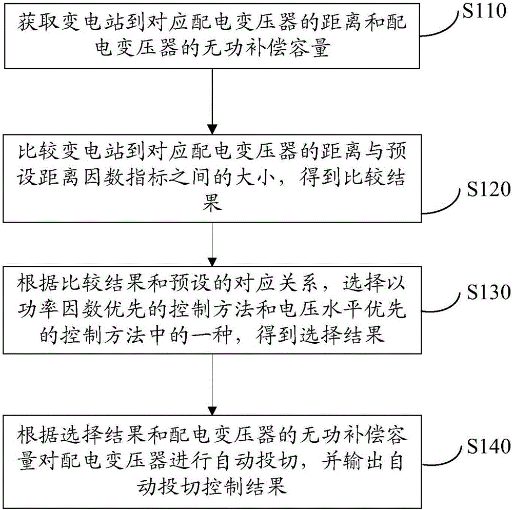
[0019] In one embodiment, such as figure 1 As shown, a passive power distribution network reactive power compensation comprehensive control method includes the following steps:

[0020] Step S110: Obtain the distance from the substation to the corresponding distribution transformer and the reactive power compensation capacity of the distribution transformer.

[0021] Specifically, the distance from the substation to the corresponding distribution transformer refers to the length of the 10kV distribution line through which the power flows from the substation 10kV bus to the corresponding distribution transformer. Reactive power compensation is an important means for the power grid to maintain a good operating condition. It can effectively improve power quality, reduce power loss and increase the utilization of power grid equipment.

[0022] Step S120: Compare the distance between the substation to the corresponding distribution transformer and the preset distance factor index to obtai...


PUM


Abstract

The invention relates to a method and a system for comprehensively controlling the reactive compensation of a passive power distribution network. The method comprises the following steps: comparing the magnitude between the distance from a transformer substation to a corresponding distribution transformer and preset distance factor indexes to obtain a comparative result by obtaining the distance from the transformer substation to the corresponding distribution transformer and the reactive compensation capacity of the distribution transformer; selecting one of a control method for prioritizing power factors and a control method for prioritizing voltage level to obtain a selection result according to the comparative result and a preset corresponding relation; and automatically switching the distribution transformer according to the selection result and the reactive compensation capacity of the distribution transformer, and outputting an automatic switching control result. By comprehensively using the relation between the distance from the transformer substation to the corresponding distribution transformer and the preset distance factor indexes and the method combined with the reactive compensation control method, the problems of power distribution network low-voltage control and area reactive balance are solved, and then the voltage quality level of the power distribution network is improved, so that the method has significant economic significance.

Description

Technical field [0001] The invention relates to the technical field of low-voltage management of passive distribution networks and regional reactive power balance, and in particular to a passive distribution network reactive power compensation comprehensive control method and system. Background technique [0002] Reactive power compensation plays a role in improving the power factor of the power grid in the power supply system, reducing the loss of power supply transformers and transmission lines, increasing power supply efficiency, and improving the power supply environment. Therefore, reactive power compensation devices are indispensable in the power supply system. Very important position missing. Reasonable selection of compensation devices can minimize the loss of the power grid and improve the quality of the power grid. On the contrary, improper selection or use may cause many factors such as the power supply system, voltage fluctuations, and increased harmonics. The speci...

Claims


Application Information

Patent Timeline
IPC IPC(8): H02J3/18
CPCY02E40/30H02J3/1821
Inventor 余加喜谢磊毛李帆吴锋黄汉昌张俊龚若飞
Owner 海南电网有限责任公司
Features
  • R&D
  • Intellectual Property
  • Life Sciences
  • Materials
  • Tech Scout
  • Unparalleled Data Quality
  • Higher Quality Content
  • 60% Fewer Hallucinations
Learn More