Device to reduce residual current

A technology of residual current and ammeter, which is applied in the direction of emergency protection circuit devices, circuit devices, emergency protection circuit devices, etc. for limiting overcurrent/overvoltage, and can solve problems such as cutting off electrical equipment

Active Publication Date: 2017-05-10
EATON IND (AUSTRIA) GMBH
View PDF9 Cites 0 Cited by
  • Summary
  • Abstract
  • Description
  • Claims
  • Application Information

AI Technical Summary

Problems solved by technology

[0003] The flaw here is that, apart from the actual source of the fault, all other parts of the electrical equipment are similarly switched off

Method used


Image

  • Device to reduce residual current

Examples


Embodiment Construction

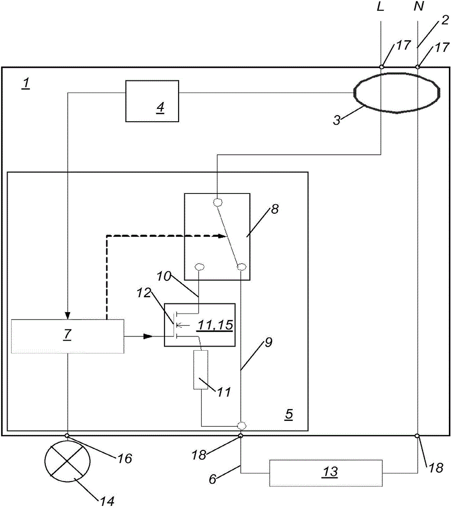
[0014] This figure shows a device 1 for reducing residual current in a circuit 2 (especially in a low-voltage electric line), wherein the device 1 has a residual current sensor 3 and an ammeter 4, wherein the output terminal of the residual current sensor 3 connected to the input of the ammeter 4, wherein the device 1 has a step-down unit 5 connected to the output of the ammeter 4, and wherein the step-down unit 5 is configured to to reduce the voltage present downstream of said device 1 in order to limit the measured residual current to a specified value, in particular 30 mA.

[0015] Thus, when a residual current occurs and its cause persists, limited operation of the electrical device 13 can be maintained if the fault leading to the ground connection is not extremely low resistance. In this way, for example, computer systems or simple lighting devices can still function. Since the mains voltage present in the switched-mode power supply can vary over a wide range, practical...


PUM


Abstract

For a device (1) for reducing residual current in an electrical circuit (2), in particular an electrical low-voltage line, wherein the device (1) has a residual current sensor (3) and a current measuring unit (4), wherein an output of the residual current sensor (3) is connected to an input of the current measuring unit (4), it is proposed that the device (1) has a voltage reducing unit (5), that the voltage reducing unit (5) is connected to an output of the current measuring unit (4), and that the voltage reducing unit (5) is designed to reduce the electrical voltage - subsequently applied to the device (1) - depending on the height of the measured residual current in order to limit the measured residual current to a predeterminable value, in particular 30 mA.

Description

technical field [0001] The invention relates to a device for reducing residual current in an electric circuit according to the preamble of claim 1 . Background technique [0002] Monitoring circuits for the occurrence of so-called residual currents or earth residual currents is a well-known procedure and is regulated by law in most countries. If the residual current is confirmed to have exceeded a given value, the circuit is cut off by the residual current circuit breaker. The specific value at which the circuit is switched off is, for example, only 30 mA, which is the limit of human ventricular fibrillation. [0003] The disadvantage here is that, apart from the actual source of the fault, all other parts of the electrical equipment are similarly switched off. In the present prevailing conditions, it is impossible to continue to operate an electrical system with such a low resistance ground connection. As soon as an attempt is made to re-start the affected circuit or the...

Claims


Application Information

Patent Timeline
IPC IPC(8): H02H9/08
CPCH02H9/08G05F1/573H02H3/08H01H83/20H01H83/144H02H9/025H02H9/02
Inventor M·科赫
Owner EATON IND (AUSTRIA) GMBH
Why Eureka
Try Eureka