A counterweight pressing device

A technology of pressing device and counterweight block, which is applied in transportation and packaging, lifting equipment in mines, etc., can solve the problems of reduced elevator operation stability and safety, reduced strength, complex structure, etc., and saves the counterweight frame. Space, improved stability, small size of the device

Active Publication Date: 2019-11-29
JIANGSU XIDE ELEVATOR
View PDF8 Cites 1 Cited by
  • Summary
  • Abstract
  • Description
  • Claims
  • Application Information

AI Technical Summary

Problems solved by technology

This compaction scheme has the following problems: 1. The structure is complex and the production efficiency is low; 2. A series of holes are opened on the straight beam, and the processing procedures are numerous and the efficiency is low; 3. After the holes are opened on the vertical beam, the strength is reduced and the elevator runs stably The performance and safety are reduced, and the wear degree of the CNC mold is increased; 4. All the bolts need to be unscrewed for disassembly and up and down adjustment of the U-shaped compression structure, which is not convenient enough
The counterweight pressing device provided by the technical solution disclosed in the above utility model has a simple structure and remarkable pressing effect, which overcomes the need to set a plurality of holes on the vertical beam in order to press the counterweight in the prior art, which causes the vertical beam to be damaged. Disadvantages of reduced strength
However, in the technical solution provided by this utility model, the pressing part is easy to tilt during operation, and the counterweight cannot be directly applied downward during the installation process. Therefore, the pressing effect needs to be improved

Method used


Image

  • A counterweight pressing device
  • A counterweight pressing device
  • A counterweight pressing device

Examples


Embodiment 1

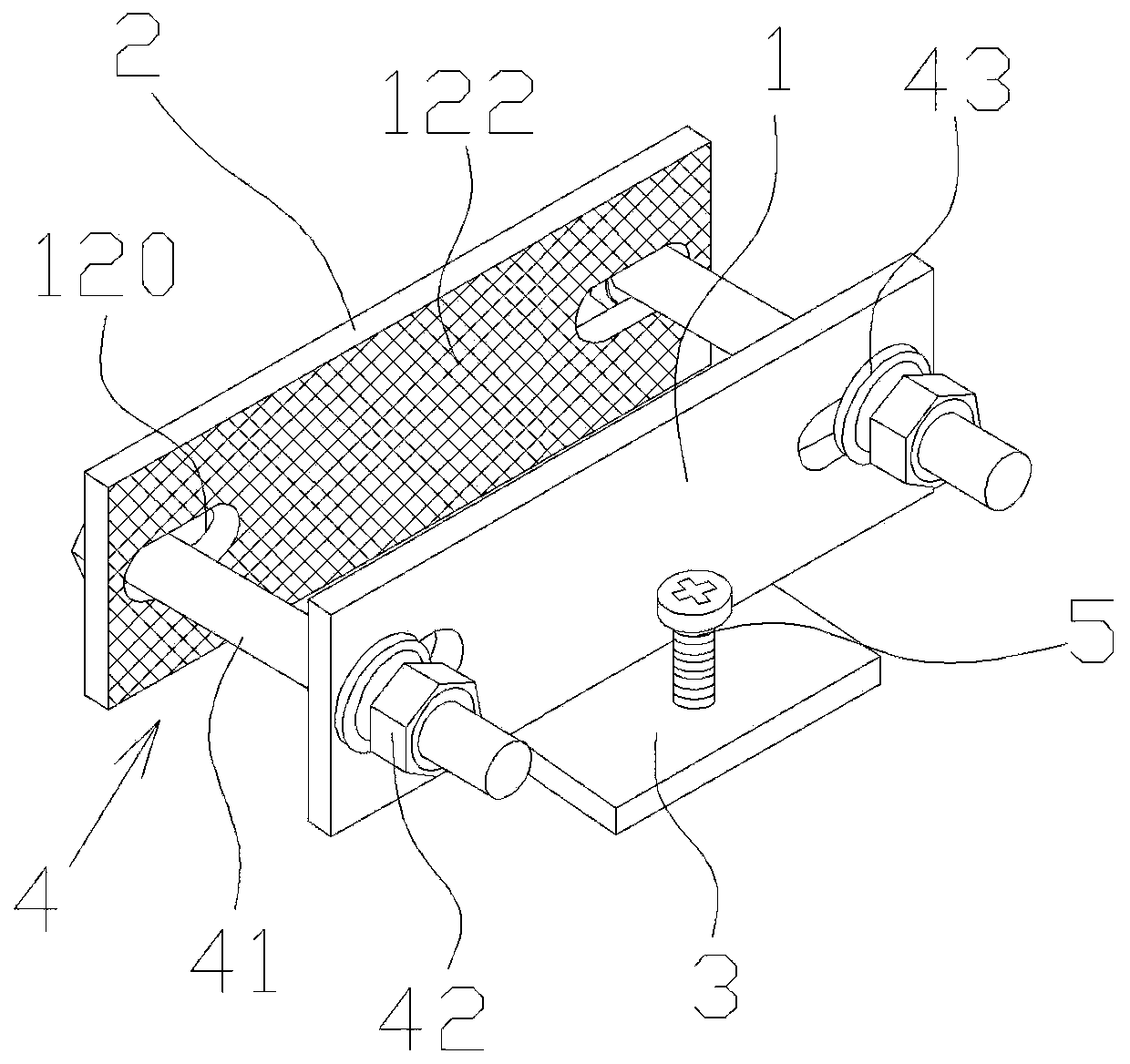
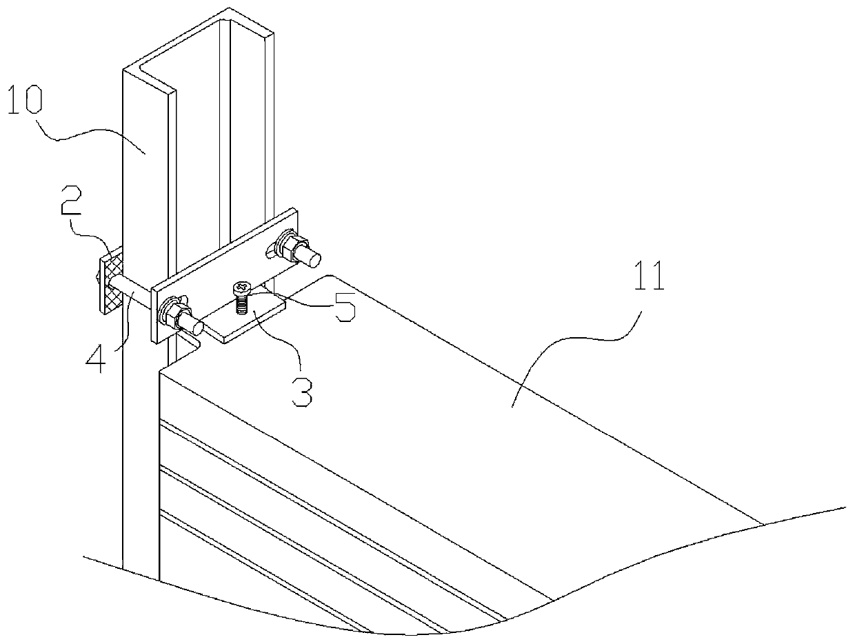
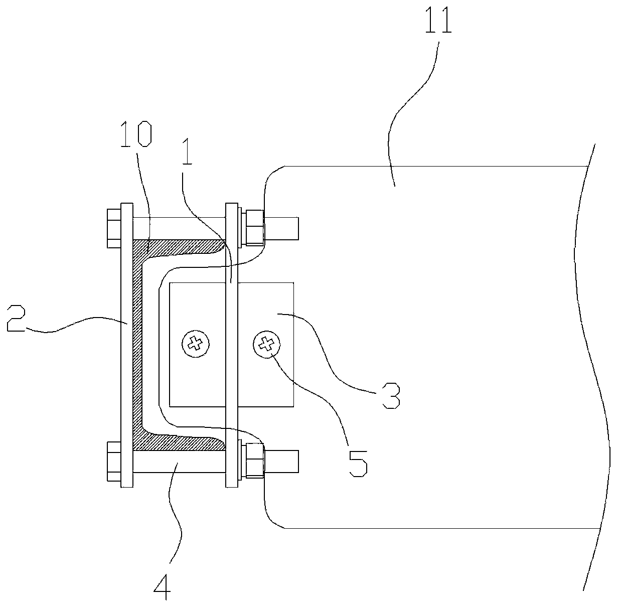
[0035] Figure 1 to Figure 3 A counterweight pressing device according to the first embodiment of the present invention is schematically shown.

[0036] Such as Figure 1 to Figure 3 As shown, a counterweight pressing device disclosed in the present invention includes a clamping mechanism for clamping the column 10 of the counterweight frame. Such as figure 2 As shown, the counterweight frame column 10 includes the left counterweight frame column and the right counterweight frame column that are arranged oppositely, and the cross sections of the left counterweight frame column and the right counterweight frame column become "U" shapes, and the left counterweight frame column and the right counterweight frame column are in the shape of "U". The openings of the right counterweight frame columns are relatively arranged, wherein the elevator counterweight block 11 is vertically stacked between the left counterweight frame column and the right counterweight frame column, and the...

Embodiment 2

[0043] Figure 4 to Figure 6 A counterweight pressing device according to the second embodiment of the present invention is schematically shown.

[0044] Such as Figure 4 to Figure 6 As shown, a kind of counterweight pressing device provided by the second embodiment of the present invention is basically the same as that in Embodiment 1, the difference is that:

[0045] Preferably, in this embodiment of the present invention, a positioning plate 6 is interposed between the front fixing splint 1 and the rear fixing splint 2 , and two positioning plates 6 are included. Such as Figure 4 As shown, on the front fixed splint 1 and the rear fixed splint 2, located on the outside of the screw hole 120, positioning slots 123 are provided respectively, wherein the positioning slots 123 on both sides of the front fixed splint 1 and the rear fixed splint 2 are in the same position, The shape and size of the aperture of the positioning slot 123 are consistent with the shape and size of...


PUM


Abstract

The invention provides a counterweight filler weight compressing device. The counterweight filler weight compressing device comprises a clamping mechanism used for clamping a counterweight housing stand column. The clamping mechanism comprises fixing clamping plates arranged on the two opposite sides of a left counterweight housing stand column body and a right counterweight housing stand column body in a clamping manner. The fixing clamping plates are locked by fixing bolt assemblies. The fixing clamping plate on one side is located above a counterweight filler weight, and the lower portion of the fixing clamping plate is connected with a fastening pressing plate which is pressed on the upper surface of the uppermost counterweight filler weight. The fastening pressing plate is connected with a first adjusting locking bolt which perpendicularly penetrates the fastening pressing plate, and the first adjusting locking bolt is in threaded connection with the fastening pressing plate. According to the counterweight filler weight compressing device, the structure that the counterweight housing stand column is inserted into the part between the fixing clamping plates is adopted, the fixing clamping plates and the counterweight housing stand column are firmly clamped by screwing the fixing bolt assemblies, the displacement, in the perpendicular direction, of the counterweight filler weight is limited by the fastening pressing plate arranged under one fixing clamping plate, and therefore the purpose of compressing the counterweight filler weight is achieved, and the compressing device is suitable for elevator counterweight housings in any height.

Description

technical field [0001] The invention relates to the technical field of elevators, in particular to a counterweight pressing device which has a stable structure and can securely fix the elevator counterweight at any position in the vertical direction of the vertical beam. Background technique [0002] The counterweight is an important part of the counterweight system. In order to ensure the smooth and comfortable operation of the elevator, the counterweight must be fixed reliably. In the prior art, a series of holes are opened on the vertical beam, and the U-shaped compression structure is fixed on the heavy straight beam through long bolts, and the U-shaped compression structure is used to press the counterweight to realize the compression of the counterweight. This compaction scheme has the following problems: 1. The structure is complex and the production efficiency is low; 2. A series of holes are opened on the straight beam, and the processing procedures are numerous and...

Claims


Application Information

Patent Timeline
Patent Type & Authority Patents(China)
IPC IPC(8): B66B17/12
CPCB66B17/12
Inventor 李博亚付西伟付年庚王东
Owner JIANGSU XIDE ELEVATOR
Why Eureka
Try Eureka