Counterweight filler weight compressing device
A technology of pressing device and counterweight block, which is applied in transportation and packaging, lifting equipment in mines, etc., can solve the problems of reduced elevator operation stability and safety, reduced strength, complex structure, etc., and saves the counterweight frame. Space, improved stability, small size of the device
- Summary
- Abstract
- Description
- Claims
- Application Information
AI Technical Summary
Problems solved by technology
Method used
Image
Examples
Embodiment 1
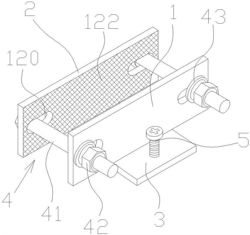
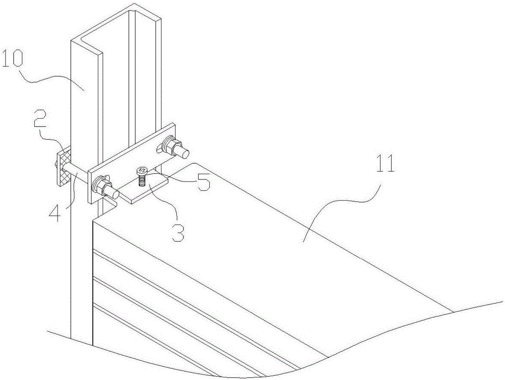
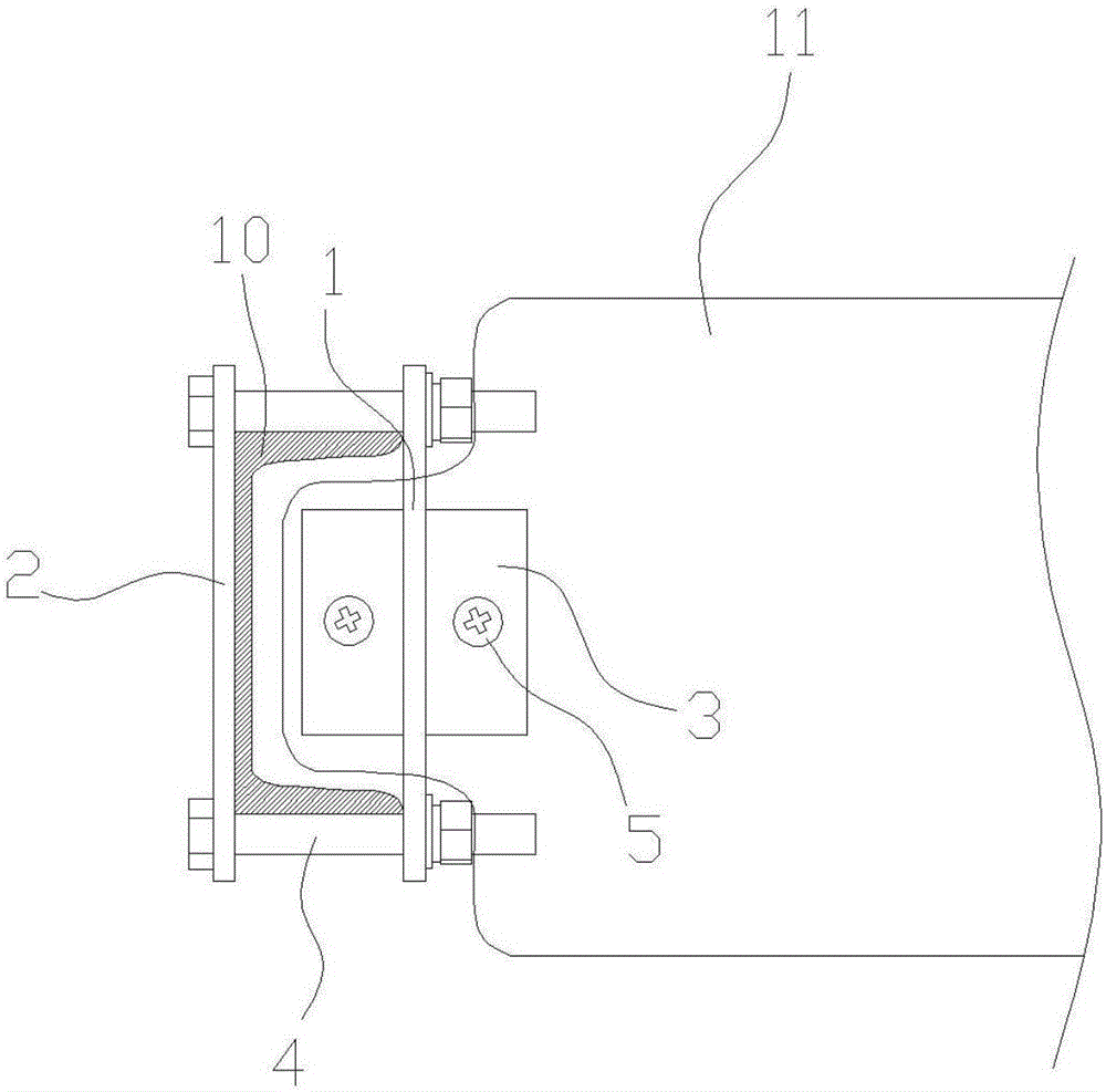
[0035] Figure 1 to Figure 3 A counterweight pressing device according to the first embodiment of the present invention is schematically shown.
[0036] Such as Figure 1 to Figure 3 As shown, a counterweight pressing device disclosed in the present invention includes a clamping mechanism for clamping the column 10 of the counterweight frame. Such as figure 2 As shown, the counterweight frame column 10 includes the left counterweight frame column and the right counterweight frame column that are arranged oppositely, and the cross sections of the left counterweight frame column and the right counterweight frame column become "U" shapes, and the left counterweight frame column and the right counterweight frame column are in the shape of "U". The openings of the right counterweight frame columns are relatively arranged, wherein the elevator counterweight block 11 is vertically stacked between the left counterweight frame column and the right counterweight frame column, and the...
Embodiment 2
[0043] Figure 4 to Figure 6 A counterweight pressing device according to the second embodiment of the present invention is schematically shown.
[0044] Such as Figure 4 to Figure 6 As shown, a kind of counterweight pressing device provided by the second embodiment of the present invention is basically the same as that in Embodiment 1, the difference is that:
[0045] Preferably, in this embodiment of the present invention, a positioning plate 6 is interposed between the front fixing splint 1 and the rear fixing splint 2 , and two positioning plates 6 are included. Such as Figure 4 As shown, on the front fixed splint 1 and the rear fixed splint 2, located on the outside of the screw hole 120, positioning slots 123 are provided respectively, wherein the positioning slots 123 on both sides of the front fixed splint 1 and the rear fixed splint 2 are in the same position, The shape and size of the aperture of the positioning slot 123 are consistent with the shape and size of...
PUM
 Abstract
Description
Claims
Application Information
 - R&D
- Intellectual Property
- Life Sciences
- Materials
- Tech Scout
- Unparalleled Data Quality
- Higher Quality Content
- 60% Fewer Hallucinations
Browse by: Latest US Patents, China's latest patents, Technical Efficacy Thesaurus, Application Domain, Technology Topic, Popular Technical Reports.
© 2025 PatSnap. All rights reserved.Legal|Privacy policy|Modern Slavery Act Transparency Statement|Sitemap|About US| Contact US: help@patsnap.com


