Fully-automatic gasket-adding equipment for medical bottle cap sealing gaskets
A sealing gasket, fully automatic technology, applied in the field of automatic padding equipment for medical bottle cap sealing gaskets, can solve problems such as troublesome operation, and achieve the effect of saving manpower
- Summary
- Abstract
- Description
- Claims
- Application Information
AI Technical Summary
Problems solved by technology
Method used
Image
Examples
Embodiment 1
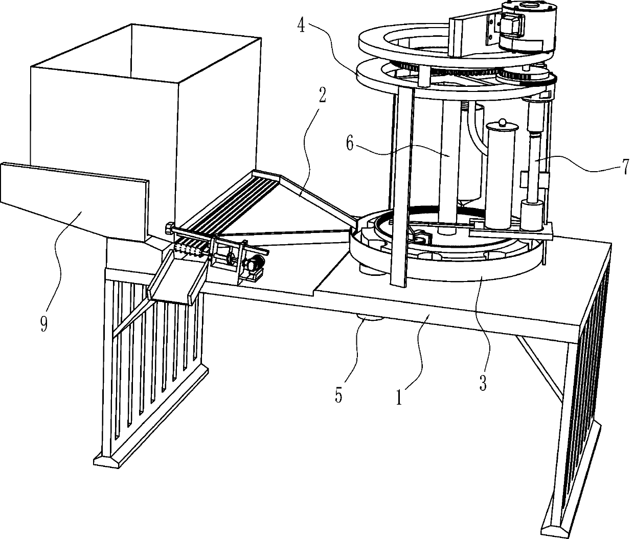
[0022] A kind of automatic cushioning equipment for sealing gaskets of medicine bottle caps, such as Figure 1-3 As shown, it includes a frame 1, a loading tray 2, a disc 3, a support 4 and a feeding tube 5, and the top of the frame 1 is connected with a loading tray 2 and a disc 3, and the discharge position of the loading tray 2 is the same as Disc 3 is connected, frame 1 top is also connected with support 4, disc 3 is located in support 4, is connected with feeding pipe 5 on frame 1, and the material inlet of feeding pipe 5 is positioned at below disc 3, and the feeding The discharge port of the pipe 5 passes through the frame 1, and also includes a feeding mechanism 6 and a pressing mechanism 7. The support 4 is provided with a feeding mechanism 6 and a pressing mechanism 7, and the feeding mechanism 6 and the pressing mechanism 7 are connected in transmission.
[0023] The feeding mechanism 6 includes a reduction motor 61, the first tooth-missing gear 62, a feeding trough...
Embodiment 2
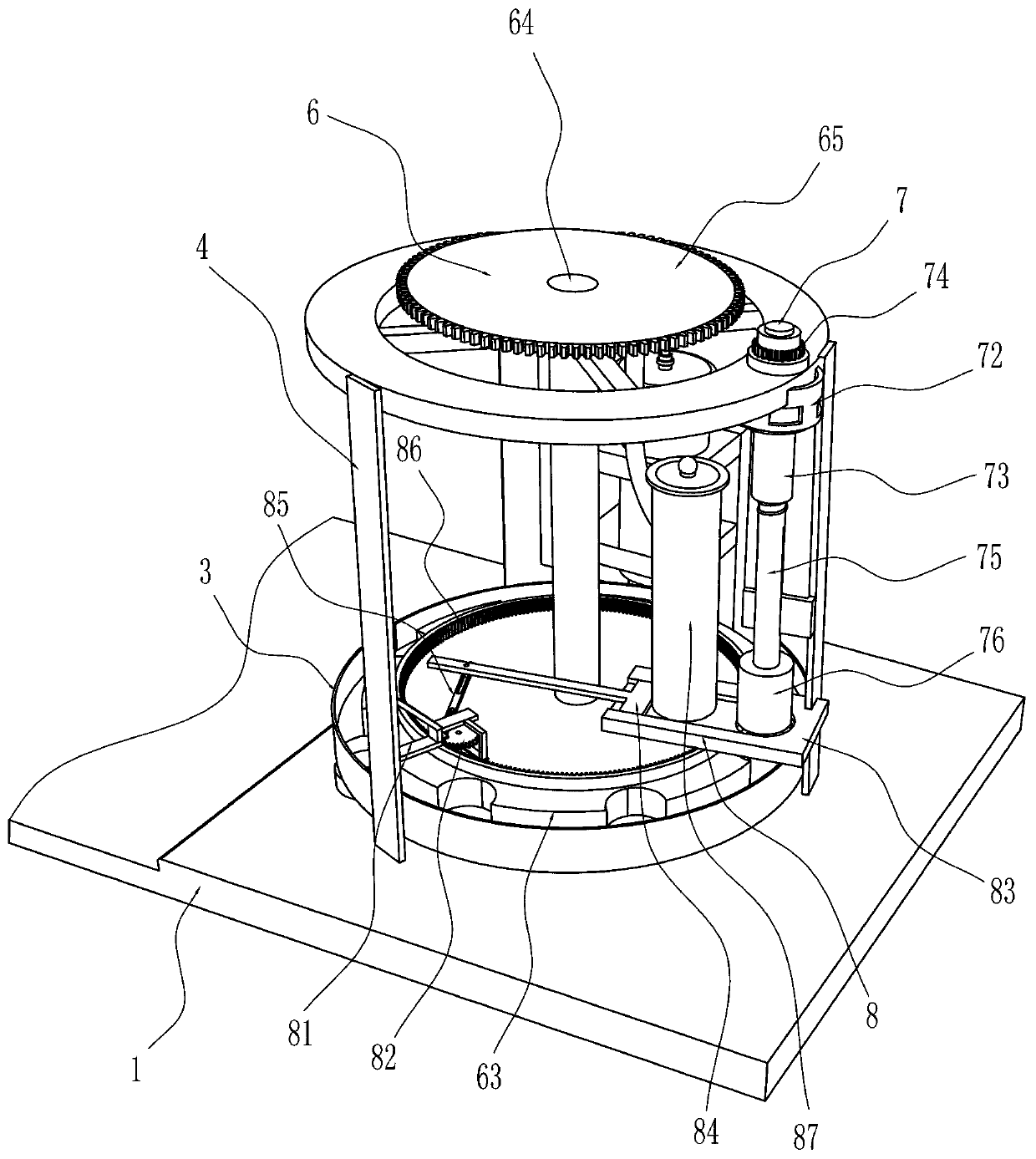
[0027] On the basis of Example 1, such as figure 2 As shown, a gasket adding mechanism 8 is also included, and the gasket adding mechanism 8 includes a connecting frame 81, a pinion 82, a guide plate 83, a push rod 84, a connecting rod 85 and a ring gear 86, and the lower part of the bracket 4 is connected with a connection Frame 81, connecting frame 81 is connected with pinion 82 in a rotating manner, and the bottom of support 4 is connected with guide plate 83, and guide plate 83 is positioned at the lower pressing block 76 below, has a through groove on the guiding plate 83, and the through groove is positioned at lower pressing block 76 Directly below, the through slot is located directly above one of the placement slots, the guide plate 83 is slidably connected with a push rod 84, the connecting frame 81 is hingedly connected with a connecting rod 85, and the connecting rod 85 is slidingly matched with the pinion 82, and the connecting rod 85 is connected with the pinion ...
Embodiment 3
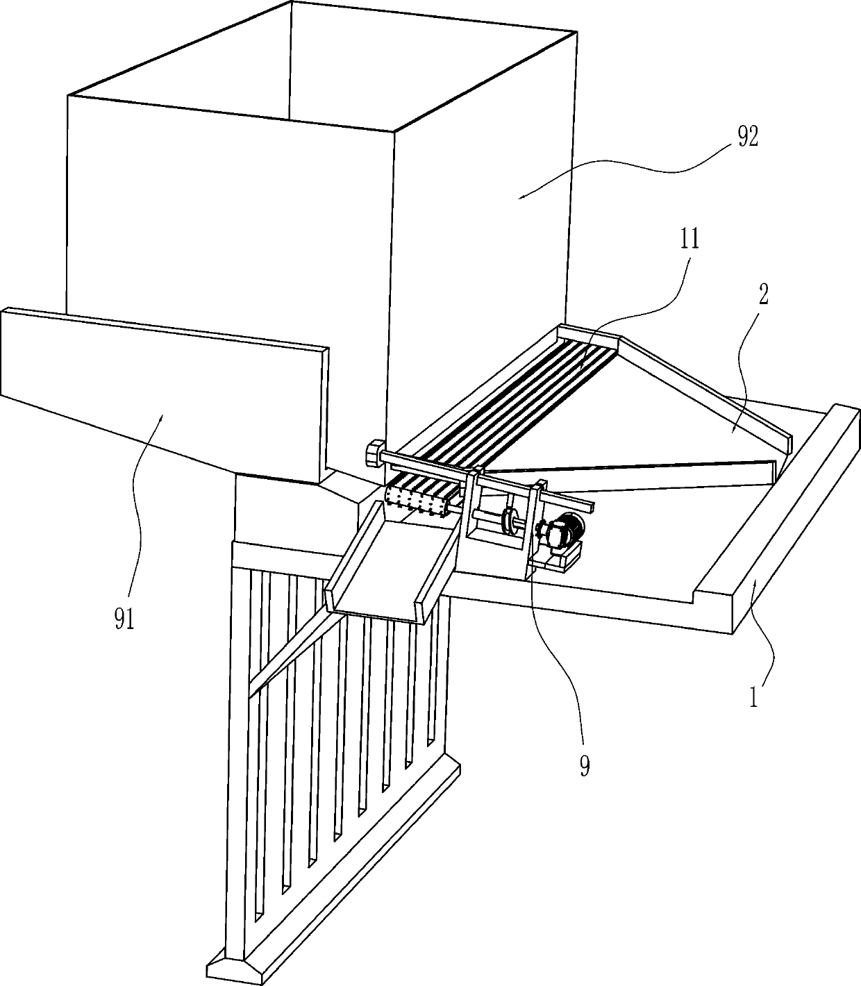
[0030] On the basis of Example 2, such as Figure 4-5 Shown, also includes unloading mechanism 9, and unloading mechanism 9 includes sliding seat 91, material storage frame 92, mounting bracket 93, servo motor 94, transmission shaft 95, sheave 96 and guide bar 97, frame 1 top The left side is connected with a sliding seat 91, and the sliding seat 91 is slidingly connected with a material storage frame 92, and the discharge position of the material storage frame 92 is aligned with the loading tray 2, and the top of the frame 1 on the right side of the sliding seat 91 is connected with a mounting frame 93, a servo motor 94 is installed on the mounting frame 93, a transmission shaft 95 is connected on the output shaft of the servo motor 94, a sheave 96 is connected on the transmission shaft 95, a guide rod 97 is slidingly connected on the mounting frame 93, and the guide rod 97 Cooperating with the sheave 96, the guide rod 97 is connected with the material storage frame 92.
[0...
PUM
 Abstract
Description
Claims
Application Information
 - R&D
- Intellectual Property
- Life Sciences
- Materials
- Tech Scout
- Unparalleled Data Quality
- Higher Quality Content
- 60% Fewer Hallucinations
Browse by: Latest US Patents, China's latest patents, Technical Efficacy Thesaurus, Application Domain, Technology Topic, Popular Technical Reports.
© 2025 PatSnap. All rights reserved.Legal|Privacy policy|Modern Slavery Act Transparency Statement|Sitemap|About US| Contact US: help@patsnap.com


