Floor assembly and installation method

A component and floor technology, which is applied in the field of floor components and installation, can solve the problems of substandard construction quality, high construction technical requirements, and long construction period, and achieve the benefits of later maintenance and replacement, low construction technical requirements, and short construction period Effect

Active Publication Date: 2017-05-17
ZHEJIANG YASHA DECORATION
View PDF7 Cites 6 Cited by
  • Summary
  • Abstract
  • Description
  • Claims
  • Application Information

AI Technical Summary

Problems solved by technology

[0003] This traditional brick laying method has the following defects: First, for the traditional brick laying method, in the positioning process of facing bricks, it is done by workers relying on their experience, and the problem of inaccurate positioning often occurs; second, the difficulty of construction Large, high requirements for construction technology, inexperienced or inexperienced workers are likely to cause problems such as substandard construction quality; third, the process is complex and the construction period is long, from the preparation before laying to the final maintenance work, you need to go through various This kind of complicated process can be completed. Since the curing time of cement mortar is generally more than seven days, the construction period is relatively long, and the construction environment is harsh, so it is impossible to achieve rapid laying; fourth, this laying method is not conducive to later maintenance and replacement, even if only one of them One piece is damaged and a large area needs to be replaced

Method used


Image

  • Floor assembly and installation method
  • Floor assembly and installation method
  • Floor assembly and installation method

Examples


Embodiment Construction

[0026] The present invention will be described in detail below in conjunction with examples. Wherein the same components are denoted by the same reference numerals. It should be noted that the words "front", "rear", "left", "right", "upper" and "lower" used in the following description refer to the directions in the drawings, and the words "inner" and "outer ” refer to directions towards or away from the geometric center of a particular part, respectively.

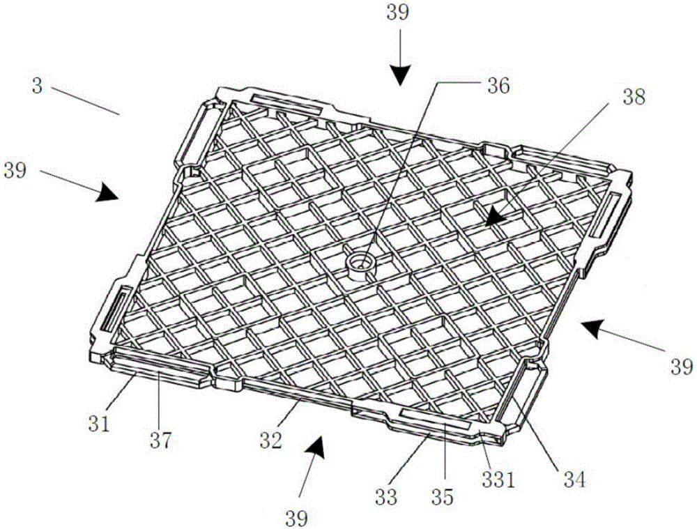
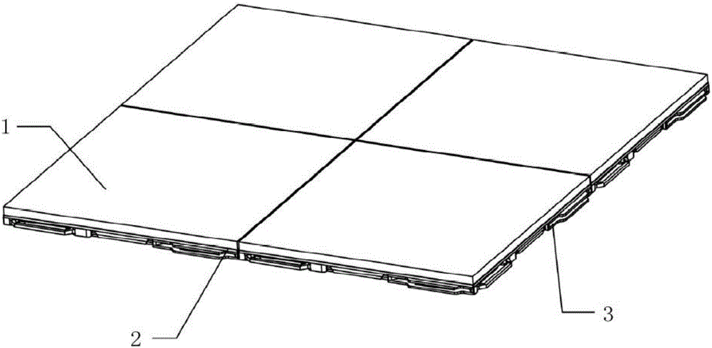
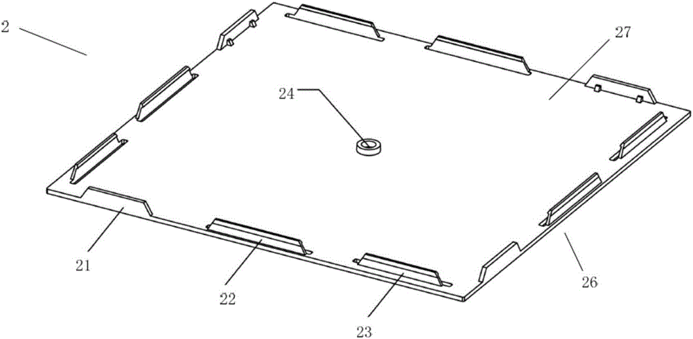
[0027] Such as Figure 1-8 As shown, the floor assembly provided by the embodiment of the present invention includes: a decorative tile 1 , an installation plate 2 and a limiting frame 3 . In general, for the floor assembly provided by the embodiment of the present invention, the limiting frame 3 is flatly laid on the ground, and the limiting frames 3 are plugged and fixed by horizontal plugging. 1 is prefabricated and pasted on the installation board 2. When laying, it is only necessary to vertically plug the assembly ...


PUM


Abstract

The invention discloses a floor assembly and an installation method. The floor assembly comprises at least two limiting frames and installation plates, wherein the limiting frames are horizontally laid on the ground, and the installation plates correspond to the limiting frames one to one; the limiting frames are horizontally laid in an inserted mode, and at least one edge of each limiting frame is provided with a protruded transverse bar and a limiting groove; each installation plate comprises a bonding face and an installation face, wherein the bonding face is used for bonding a face brick, the installation face is back to the bonding face, and the installation faces are attached to limiting faces; and blocking walls are installed on the installation faces, and the blocking walls are connected with the protruded transverse bars and the limiting grooves in a clamping mode. The installation method comprises the following steps that the face bricks are bonded to the bonding faces of the installation plates; the limiting frames are horizontally laid on the ground so that the limiting frames can be horizontally inserted; and the installation plates are installed on the limiting frames. According to the floor assembly and the installation method provided by the embodiment of the invention, construction is simple, positioning is quick and accurate, the construction period is short, the construction site is not polluted, and maintenance and replacement at the later period are facilitated.

Description

technical field [0001] The invention relates to the technical field of floor decoration, in particular to a floor assembly and an installation method. Background technique [0002] At present, in the floor decoration industry, the paving of stone and ceramic tiles is generally realized by wet paving. One of the typical processes is as follows: first clean the base layer, spread the cement mortar mixed according to a certain proportion on the base layer, and spread the facing bricks on the cement mortar; then, use a leather hammer to knock the facing bricks flat and firm ; After the cement mortar dries, the facing brick will be firmly fixed on the base. [0003] This traditional brick laying method has the following defects: First, for the traditional brick laying method, in the positioning process of facing bricks, it is done by workers relying on their experience, and the problem of inaccurate positioning often occurs; second, the difficulty of construction Large, high re...

Claims


Application Information

Patent Timeline
Patent Type & Authority Applications(China)
IPC IPC(8): E04F15/02E04F21/22
CPCE04F15/02E04F21/22
Inventor 周东珊步挺余文钊武鹏李梦珺
Owner ZHEJIANG YASHA DECORATION
Why Eureka
Try Eureka