
Medical lamp device

A technology of medical lamps and equipment, applied in the field of medical lamps, can solve problems such as safety hazards, cumbersome operation, inconvenience, etc., achieve the effects of improving safety and reliability, realizing automatic operation, and avoiding the risk of electric shock

Inactive Publication Date: 2017-05-17
江苏泓睿德智能科技有限公司
View PDF5 Cites 6 Cited by
  • Summary
  • Abstract
  • Description
  • Claims
  • Application Information

AI Technical Summary

Problems solved by technology

[0002] At present, the use of medical lamps is more common. Since the medical lamp itself has a certain height, the safe insertion during use is an important guarantee for the personal safety of the user. The medical lamps in the prior art are generally inserted manually. In the process of plugging, the plugging is often unreliable, so that the blades on the plug are not fully inserted into the socket. In this case, electric shock accidents are most likely to occur, and there are great potential safety hazards. For their own safety, people often choose, first Disconnect the main power supply and then insert the plug into the socket and finally turn on the power. The operation is too cumbersome and brings great inconvenience to the user.

Method used


Image

  • Medical lamp device
  • Medical lamp device
  • Medical lamp device

Examples


Embodiment Construction

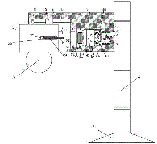
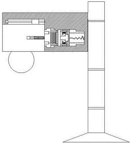
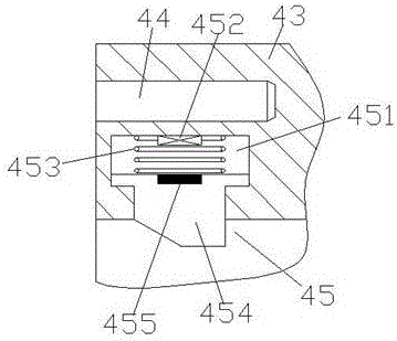
[0023] Such as Figure 1-Figure 5 As shown, a medical light device of the present invention includes a lamp holder 1 and a lamp holder 2. The lamp holder 1 is composed of an abutment portion 11 and a base portion 12. The abutment portion 11 is provided with a first screw rod 14. The first screw rod 14 is provided with a sliding block 13, and the first screw rod 14 is extended to both sides, and the left extended end of the first screw rod 14 is rotatably connected with a first motor 15, so The extended end on the right side of the first screw rod 14 is rotatably connected to the base part 12, the bottom end of the sliding block 13 is fixedly connected to the lamp cap 2, and the right end surface of the lamp cap 2 is provided with an insert piece 21. The lower end of the lamp cap 2 is provided with a light bulb 8, and the base part 12 is provided with a second sliding cavity 3, a power distribution compartment 4 and a circuit cavity 5 corresponding to the lamp cap 2 from left t...


PUM


Abstract

The invention discloses a medical lamp device which comprises a lamp seat and a lamp cap. The lamp seat is composed of a butt joint part and a base part. A first screw rod is arranged in the butt joint part, and a sliding block is arranged on the first screw rod. The first screw rod extend towards the two sides, the extending end of the left side of the first screw rod is rotationally matched and connected with a first motor, and the extending end of the right side of the first screw rod is rotationally connected with the base part. The bottom end of the sliding block is fixedly connected with the lamp cap. An insertion piece is arranged on the end face of the right side of the lamp cap, and a bulb is arranged at the lower end of the lamp cap. A second sliding cavity, a distribution bin and a circuit cavity which correspond to the lamp cap are arranged in the base part one by one from left to right. The medical lamp device is simple in structure, the possibility that the accident electric shock is caused in a non-connecting manner can be effectively prevented, automatic connecting control can be achieved, the connecting stability is improved, and the possibility that the electric shock is caused by person contact is lowered.

Description

technical field [0001] The invention relates to the technical field of medical lights, in particular to a medical light device. Background technique [0002] At present, the use of medical lamps is more common. Since the medical lamp itself has a certain height, the safe insertion during use is an important guarantee for the personal safety of the user. The medical lamps in the prior art are generally inserted manually. In the process of plugging, the plugging is often unreliable, so that the blades on the plug are not fully inserted into the socket. In this case, electric shock accidents are most likely to occur, and there are great potential safety hazards. For their own safety, people often choose, first Disconnecting the main power supply and then inserting the plug into the socket and finally turning on the power, the operation is too complicated and brings great inconvenience to the user. Contents of the invention [0003] The technical problem to be solved by the p...

Claims


Application Information

Patent Timeline
Patent Type & Authority Applications(China)
IPC IPC(8): F21S8/00F21V21/35F21V23/06
CPCF21S8/00F21V21/35F21V23/06
Inventor 朱晓凤
Owner 江苏泓睿德智能科技有限公司
Learn More