
local DIMMING backlight drive circuit and electronic equipment

A backlight drive circuit and drive power technology, applied to static indicators, instruments, etc., can solve the problems of high cost and complicated circuit design

Active Publication Date: 2019-12-03
SHENZHEN TCL DIGITAL TECH CO LTD
View PDF5 Cites 0 Cited by
  • Summary
  • Abstract
  • Description
  • Claims
  • Application Information

AI Technical Summary

Problems solved by technology

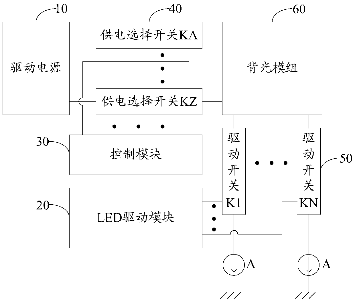
[0004] The main purpose of the present invention is to propose a LOCAL DIMMING backlight drive circuit and electronic equipment, aiming to solve the problem that the LOCAL DIMMING backlight drive circuit in the prior art uses more drive ICs to simultaneously drive multiple drive switches, resulting in complicated circuit design and cost. higher question

Method used


Image

  • local DIMMING backlight drive circuit and electronic equipment
  • local DIMMING backlight drive circuit and electronic equipment
  • local DIMMING backlight drive circuit and electronic equipment

Examples


Embodiment Construction

[0034] The following will clearly and completely describe the technical solutions in the embodiments of the present invention with reference to the accompanying drawings in the embodiments of the present invention. Obviously, the described embodiments are only part of the embodiments of the present invention, not all of them. Based on the embodiments of the present invention, all other embodiments obtained by persons of ordinary skill in the art without creative efforts fall within the protection scope of the present invention.

[0035] It should be noted that if there is a directional indication (such as up, down, left, right, front, back...) in the embodiment of the present invention, the directional indication is only used to explain the position in a certain posture (as shown in the accompanying drawing). If the specific posture changes, the directional indication will also change accordingly.

[0036] In addition, if there are descriptions involving "first", "second" and ...


PUM


Abstract

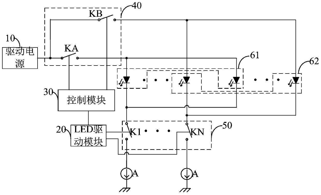
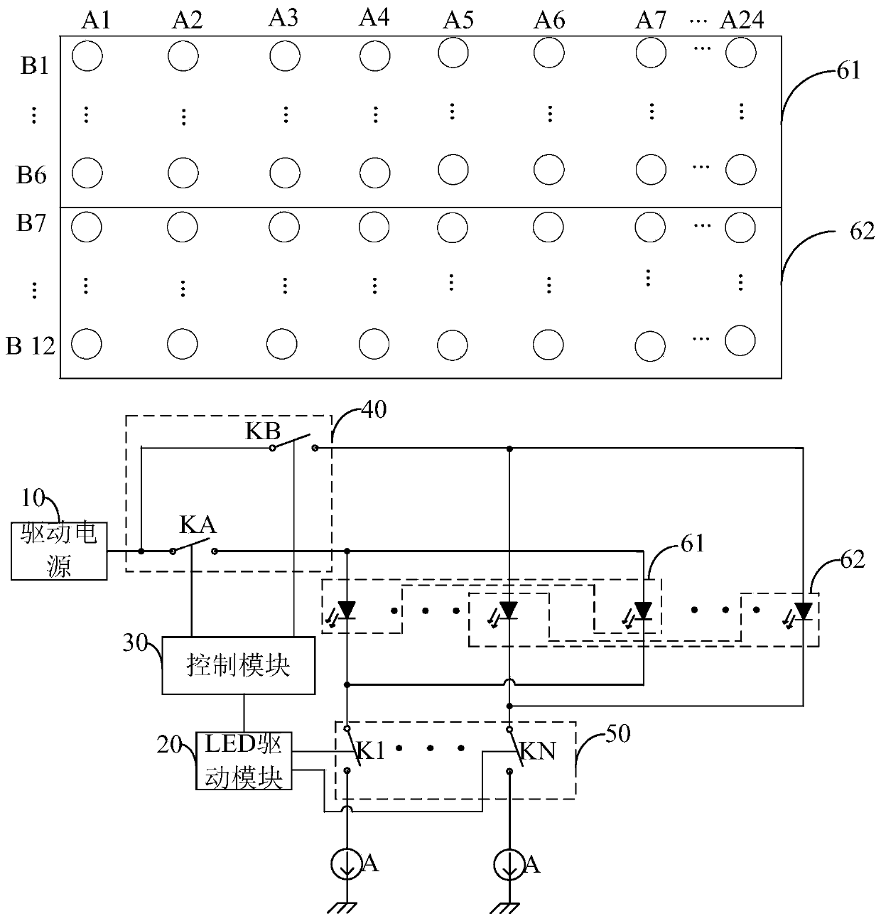
A local dimming backlight driver circuit and an electronic device, the local dimming backlight driver circuit comprising: a current sink (A); a driver power source (10); a backlight module (60), the backlight module (60) comprising multiple LED lamps arranged in a matrix; multiple power supply selector switches (40), input terminals of the multiple power supply selector switches (40) being connected to the driver power source (10); output terminals of the multiple power supply selector switches (40) being connected to anodes of the LED lamps in a one-to-one correspondence; multiple driver switches (50), an input terminal of each driver switch (50) being connected to cathodes of at least two LED lamps, and an output terminal of each driver switch (50) being grounded via the current sink (A); and a control module (30), used to drive each driver switch (50), so as to implement dimming of an LED driver module (20), control LED driver module (20) operation and control the multiple power supply selector switches (40) to turn on and off. The present local dimming backlight driver circuit decreases a number of driver ICs, lowering production costs.

Description

technical field [0001] The invention relates to the technical field of backlight driving, in particular to a LOCAL DIMMING backlight driving circuit and electronic equipment. Background technique [0002] At present, in the LOCAL DIMMING drive technology, the driver IC generally drives an LED light by adjusting the duty ratio of a drive switch, so that each LED light passes a constant current, thereby changing the brightness of each LED light. [0003] The above-mentioned driving method adopts many driving switches, and the pins of the driving IC are limited, therefore, more driving ICs are needed to drive multiple driving switches at the same time, the circuit design is complicated and the cost is high. Contents of the invention [0004] The main purpose of the present invention is to propose a LOCAL DIMMING backlight drive circuit and electronic equipment, aiming to solve the problem that the LOCAL DIMMING backlight drive circuit in the prior art uses more drive ICs to s...

Claims


Application Information

Patent Timeline
Patent Type & Authority Patents(China)
IPC IPC(8): G09G3/34
CPCG09G3/3406G09G3/342
Inventor 杨福军王坚
Owner SHENZHEN TCL DIGITAL TECH CO LTD
Learn More