Sand box capable of rotating in liftable way

A technology of sand box and lifting rod, which is used in mold boxes, casting equipment, metal processing equipment, etc., can solve the problems of heavy, unsafe, and troublesome castings and sand boxes.

Inactive Publication Date: 2017-05-24
句容市有色金属铸造厂
View PDF8 Cites 1 Cited by
  • Summary
  • Abstract
  • Description
  • Claims
  • Application Information

AI Technical Summary

Problems solved by technology

Castings and sand boxes are heavy. When pouring, the container for molt

Method used


Image

  • Sand box capable of rotating in liftable way

Examples


Embodiment

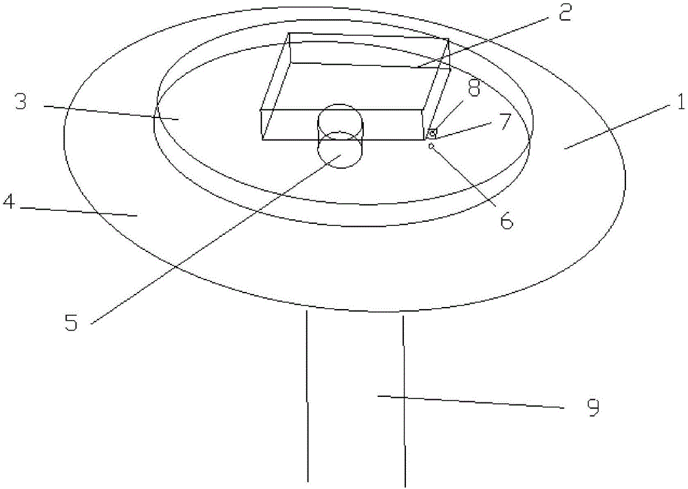
[0013] Such as figure 1 , a sand box that can be lifted and rotated in this embodiment includes a turntable 1, a sand box 2, a rotating table 3, a fixed table 4, a rotating bearing 5, a screw hole 6, a connecting plate 7, a through hole 8 and a lifting rod 9 ; The sandbox is detachably set on the turntable 1. The bottom of the turntable is provided with a lifting rod 9.

[0014] The turntable includes a rotary table 3 and a fixed table 4 , and the rotary table and the fixed table are connected by a rotary bearing 5 .

[0015] A screw hole 6 is provided on the turntable, and a connection plate 7 is provided at the bottom of the sand box, and a through hole 8 adapted to the screw hole is provided on the connection plate, and the screw hole and the through hole are connected and fixed by bolts.

[0016] The lifting rod is an electric lifting rod.

[0017] When this embodiment is in use, the prepared sand box 2 is fixed on the turntable 1 by bolts, and then casts. When the spru...


PUM


Abstract

The invention provides a sand box capable of rotating in a liftable way. The sand box comprises a rotating disk and a sand box body, and the sand box body is detachably arranged on the rotating disk. The rotating disk comprises a rotating platform and a fixed platform which are connected by a rotating bearing. A screw hole is formed in the rotating platform, the bottom of the sand box body is provided with a connecting plate in which a through hole adapted to the screw hole is formed, the screw hole is connected and fixed together with the through hole by a bolt, and the bottom of the rotating disk is provided with a lifting rod. The lifting rod is an electric lifting rod. The sand box body is arranged on the rotating disk, the lifting rod is arranged under the rotating disk, and the height of the sand box body and the position of a sprue can be regulated by rotating the rotating disk and keeping a molten iron vessel fixed during pouring, so that the sand box is labor-saving and safe.

Description

technical field [0001] The invention relates to the field of casting, in particular to a sand box that can be lifted and rotated. Background technique [0002] The gate, also known as the feed port or the inner channel, is the narrow part of the runner and the plastic part. In injection and transfer molding molds, a cavity with more than one gate is called multi-gate. Castings and sand boxes are heavy, and when pouring, usually the container of molten iron moves, which is not only troublesome but also unsafe. Contents of the invention [0003] Purpose of the invention: The technical problem to be solved by the present invention is to provide a sand box that can be lifted and rotated in view of the deficiencies of the prior art. [0004] In order to solve the above technical problems, the present invention provides a flask that can be lifted and rotated, including a turntable and a flask, and the flask is detachably arranged on the turntable. [0005] In the present inve...

Claims


Application Information

Patent Timeline
IPC IPC(8): B22C21/12
CPCB22C21/12
Inventor 朱观友
Owner 句容市有色金属铸造厂
Why Eureka
Try Eureka