Combined Drill Bit for High Jet Mixing Cement and Soil Pile

A cement-soil pile and combined technology, which is applied in the direction of drill bit, earth square drilling, sheet pile wall, etc., can solve the problems of no inspection hole, poor ground adaptability, mud inclusion phenomenon, etc., so as to improve construction efficiency and stratum adaptability Strong and reduce the effect of drilling resistance

Active Publication Date: 2018-09-25
山东省建筑科学研究院有限公司 +1
View PDF10 Cites 0 Cited by
  • Summary
  • Abstract
  • Description
  • Claims
  • Application Information

AI Technical Summary

Problems solved by technology

The nozzle of this drilling tool is fixed and has no combination function. The drill bit form cannot be adjusted according to the formation conditions. The adaptability is poor. The nozzle does not protrude along the pile diameter in a stepped shape, and the grouting in the cross section of the pile is not uniform.
[0013] A comprehensive analysis of the above drill bits for pile foundation construction mainly has the following shortcomings: (1) The nozzle of the drilling tool is fixed, the spray angle cannot be adjusted, there is no combination function, and the formation adaptability is poor; (2) The extension length of the stirring fin and the nozzle cannot be adjusted according to the pile diameter, The diameter of the pile cannot be guaranteed; (3) The nozzle of the drill bit is not arranged in steps along the diameter of the pile, and the grouting in the cross section of the pile body is uneven, and mud may be trapped; (4) There is no inspection hole, and the inspection and maintenance of the drill bit is inconvenient

Method used


Image

  • Combined Drill Bit for High Jet Mixing Cement and Soil Pile
  • Combined Drill Bit for High Jet Mixing Cement and Soil Pile
  • Combined Drill Bit for High Jet Mixing Cement and Soil Pile

Examples


Embodiment 1

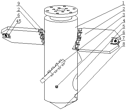
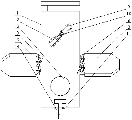
[0050] Embodiment 1: as figure 1 , 2 , 3, a combined drill bit suitable for high-jet mixing cement-soil piles, it includes a drill body 1 that is hollow cylindrical and has a built-in air path and a slurry path. One first stirring fin 2 and two second stirring fins 3, the first stirring fin 2 is located above the second stirring fin 3, the projections of the first stirring fin 2 and the second stirring fin 3 on the horizontal plane are perpendicular to each other; The lower part of the outer wall of the main body 1 is located below the second stirring fin 3 and is provided with a second nozzle 4 .

[0051] like Image 6 As shown, a drill pipe bolt hole 21, an air inlet hole 22 and a slurry inlet hole 23 are arranged on the top of the drill body 1, and a first stirring fin mounting plate 30 and a second stirring fin mounting plate are arranged on the outer wall of the drill bit body 1. 26. There are bolt holes on the first stirring fin mounting plate 30 and the second stirri...

Embodiment 2

[0066] Embodiment 2: The similarities between this embodiment and Embodiment 1 will not be repeated, and the difference is:

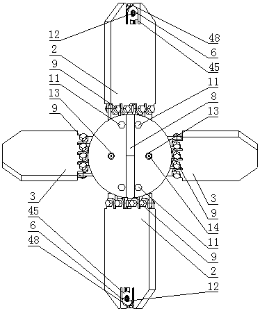
[0067] like Figure 11 , 13 , 15, the basic structure of the first stirring fin 2 and the second stirring fin 3 adopts the rake-tooth structure, and the first stirring fin 2 includes a central steel rod 41 which is hollow and horizontally arranged, and on the central steel rod 41 Several longitudinally long steel rods 42 are arranged, the middle part of the longitudinally long steel rods 42 intersects the central steel rod 41 perpendicularly, the two ends of the longitudinally long steel rods 42 are provided with tapered tips, and on the outermost one longitudinally long steel rods 42 Two horizontal short steel rods 43 are provided, one end of the horizontal short steel rod 43 is connected with the vertical long steel rod 42, and the other end is provided with a tapered tip, and the horizontal short steel rod 43 is provided with a Longitudinal short s...

Embodiment 3

[0072] A method for using a combined drill bit suitable for high jet mixing cement-soil piles, comprising the following steps:

[0073] (1) Determine the diameter of the drill according to the design documents. If there is a stirring fin with a diameter that meets the requirements after being connected to the drill body 1, then directly select it. If there is no stirring fin of suitable size to choose from, the stirring fin that meets the requirements can be manufactured without reprocessing the entire drill bit.

[0074] (2) Judging the softness and hardness of the local stratum according to the survey report. If the formation is soft, the first nozzle 7 can be adjusted to spray upwards; if the formation is moderately soft and hard, the first nozzle 7 can be adjusted to spray horizontally; if the formation is hard, the first nozzle 7 can be adjusted to spray downward.

[0075] (3) Connect the drill pipe 46 and the drill bit body through the bolt 47, and connect the grouting ...


PUM


Abstract

The invention discloses a combined type drill applicable to a high-spray stirring cement pile. The combined type drill comprises a hollow cylindrical drill body which is internally provided with a gas path and a slurry path, two first stirring blades and two second stirring blades are distributed oppositely on the outer wall of the drill body; the position, below the second stirring blades, of the lower portion of outer wall of the drill body, is provided with a second nozzle; the lower surface of a drill tip is provided with a third vent hole and a third nozzle; the ends, far away from the drill body, of the first stirring blades, are provided with two fixed plates, a slurry hosepipe and a gas path hosepipe, a nozzle veering seat is arranged between the two fixed plates, locating bolt holes and rolling bearing mounting holes are formed in the two fixed plates, the nozzle veering seat is in a flat cylindrical shape, mounting holes are formed in the center of the two end faces of the nozzle veering seat, a protrusion, a slurry hole and a gas hole are formed in the hook face of the nozzle veering seat, rotation shafts are fixedly arranged in the mounting holes, two ends of the rotation shafts are inserted into a rolling bearing and are tightly coordinated with the inner holes of the rolling bearing so as to achieve the pivot of the nozzle veering seat.

Description

technical field [0001] The invention relates to the technical field of construction of high-jet mixing cement-soil piles in construction engineering, in particular to a combined drill bit suitable for high-jet mixing cement-soil piles and a use method thereof. Background technique [0002] High-spray mixed cement-soil piles can be used not only to strengthen soft soil foundations such as muddy soil, saturated loess, and cohesive soil, but also to be used in conjunction with rigid piles such as pipe piles and steel piles for composite piles. High-spray mixed cement-soil piles have been widely used in foundations due to their wide application range, simple process, and low cost, and have developed rapidly. With the rapid development and application of high-jet mixing cement-soil piles, how to complete the construction of high-jet mixing cement-soil piles quickly, efficiently, and with high quality and quantity has become the focus of attention, and the decision of the construc...

Claims


Application Information

Patent Timeline
Patent Type & Authority Patents(China)
IPC IPC(8): E21B10/62E21B10/633E21B10/60E02D5/46
CPCE02D5/46E21B10/60E21B10/62E21B10/633
Inventor 宋义仲程海涛卜发东米春荣李建明朱锋韩国梁刘彬
Owner 山东省建筑科学研究院有限公司
Why Eureka
Try Eureka