Guide structure of spraying system

A technology of spraying system and deflector, which is applied in the direction of capturing or killing insects, application, animal husbandry, etc. It can solve the problems of low flexibility in the use process, poor spray effect, complex structure, etc., and achieve airflow pressure Sufficient, simple structure, enhance the effect of spraying effect

Pending Publication Date: 2018-08-31
GUANGXI HONGFA HEAVY IND MACHINE
View PDF8 Cites 0 Cited by
  • Summary
  • Abstract
  • Description
  • Claims
  • Application Information

AI Technical Summary

Problems solved by technology

[0002] With the popularization of agricultural machinery, the mechanization of spraying has gradually become common. For example, the air-driven spraying machine achieves uniform spraying by combining the action of fans and high-pressure water pumps. However, the structure of the current existing technology is too complicated and the use process is not flexible enough. High and poor spray effect

Method used


Image

  • Guide structure of spraying system
  • Guide structure of spraying system
  • Guide structure of spraying system

Examples


specific Embodiment 1

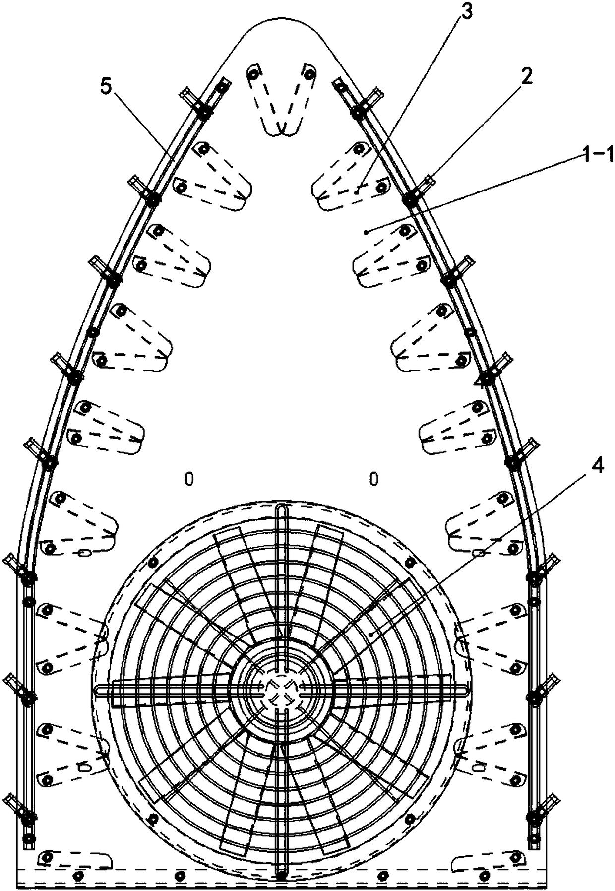
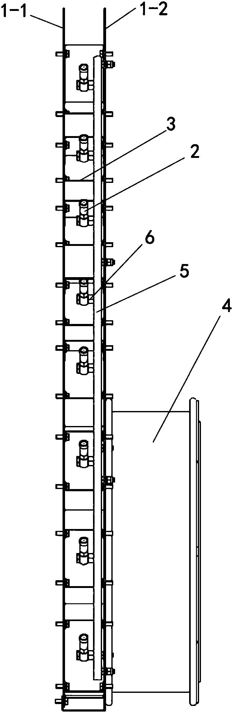
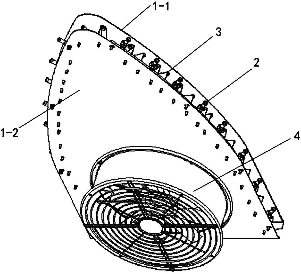
[0018] Such as Figure 1~3 As shown, a flow guide structure of a spray system includes a wind guide cover, a fan 4, an infusion pipeline 5, and a nozzle 2, and the wind guide cover includes a front cover 1-2 and a rear cover 1-1, and the front cover 1-2 Both the lower half of the cover plate 1-2 and the rear cover plate 1-1 are quadrangular, and the upper half is triangular. Adopting this structure can effectively improve the distribution uniformity of the airflow inside the windshield, especially to ensure the upper airflow Have enough pressure to ensure the overall spray effect. The lower part of the front cover 1-2 is provided with the fan 4, the nozzle 2 communicates with the infusion pipeline 5, and a plurality of "V"-shaped deflectors 3 are distributed inside the wind deflector. The plate 3 is distributed along the outer periphery of the wind deflector, and the top inside the wind deflector is distributed with a deflector 3, which also prevents strong air from blowing o...

specific Embodiment 2

[0019] The difference between this embodiment and Embodiment 1 is that: it also includes an air guide tube assembly, which is distributed behind each of the nozzles 2; the air guide tube assembly includes a flexible bellows 7 and a sealing Plate 8; the bellows 7 in this embodiment adopts a plastic bellows for guiding the wind and ensuring that it can turn. between two adjacent deflectors 3, and seal the air outlet between two adjacent deflectors 3; the rear end of the spray head 2 is connected to the The inner chamber of bellows 7 front ends is combined. When in use, the airflow inside the air guide hood can only be blown out through the bellows 7. When adjusting the direction of the nozzle as required, the plastic bellows can be bent to ensure that the wind direction is consistent with that of the nozzle and significantly improve the spraying effect.

specific Embodiment 3

[0020] The difference between this embodiment and Embodiment 1 is that the deflector is in a "U" shape, and a control valve is provided between the nozzle and the connecting pipe. Through the control valve, each The direction of the nozzle flow is controlled or closed to prevent the waste of liquid medicine.


PUM


Abstract

The invention discloses a guide structure of a spraying system. The guide structure comprises a guide hood, a fan, a liquid delivery pipeline and spray heads, wherein the guide hood comprises a fronthood plate and a rear hood plate, the fan is arranged at the lower part of the front hood plate, the spray heads are communicated with the liquid delivery pipeline, multiple U-shaped or V-shaped guideplates are distributed in the guide hood, and distributed along the periphery of the guide hood, and the spray heads are distributed between two adjacent guide plates. The guide structure is simple in structure, flexible to use, capable of realizing uniform spraying in all directions and good in spray effect.

Description

technical field [0001] The invention relates to the technical field of agricultural spray vehicles, in particular to a flow guide structure of a spray system. Background technique [0002] With the popularization of agricultural machinery, the mechanization of spraying has gradually become common. For example, the air-driven spraying machine achieves uniform spraying by combining the action of fans and high-pressure water pumps. However, the structure of the current existing technology is too complicated and the use process is not flexible enough. High and the spray effect is not good. [0003] The disclosure of the above background technical content is only used to assist in understanding the concept and technical solution of the present invention, and it does not necessarily belong to the prior art of this patent application. If there is no clear evidence that the above content has been disclosed on the filing date of this patent application In some cases, the above backg...

Claims


Application Information

Patent Timeline
Patent Type & Authority Applications(China)
IPC IPC(8): A01M7/00
CPCA01M7/0032
Inventor 李凤军林初仁邱伟廷
Owner GUANGXI HONGFA HEAVY IND MACHINE
Why Eureka
Try Eureka