Flaring out device for projection screen

A projection screen and horizontal position technology, which is applied in the field of screens, can solve the problems of affecting the leveling effect of the projection screen by the counterweight pull rod, affecting the projection effect of the projection screen, and poor projection effect of the projection screen, and achieves simple structure, improved leveling effect, and easy installation quick and easy effect

Inactive Publication Date: 2017-05-24
张家港宝视特影视器材有限公司
View PDF4 Cites 2 Cited by
  • Summary
  • Abstract
  • Description
  • Claims
  • Application Information

AI Technical Summary

Problems solved by technology

The disadvantages of the above-mentioned projection screen are: the bottom edge of the projection screen is sewn into a roll shape by a sewing machine. On the one hand, because the sewing thread of the sewing machine cannot be kept flush during the sewing process, the counterweight pull rod is inserted into the roll. Placed in a slanted shape, the weighted rods placed in a slanted shape tend to distort the projection screen, which greatly affects the leveling effect of the weighted rod on the projection screen, thereby affecting the projection effect of the projection screen; on the other hand, the projection screen rolls into After the roll shape, the lower part will inevitably curl up, which further affects the leveling effect of the counterweight rod on the projection screen, resulting in poor projection effect of the projection screen

Method used


Image

  • Flaring out device for projection screen
  • Flaring out device for projection screen
  • Flaring out device for projection screen

Examples


Embodiment Construction

[0015] The present invention will be further described below in conjunction with the accompanying drawings and specific embodiments.

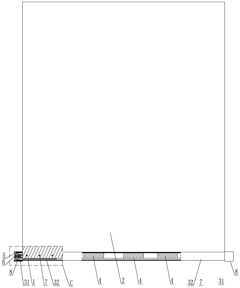
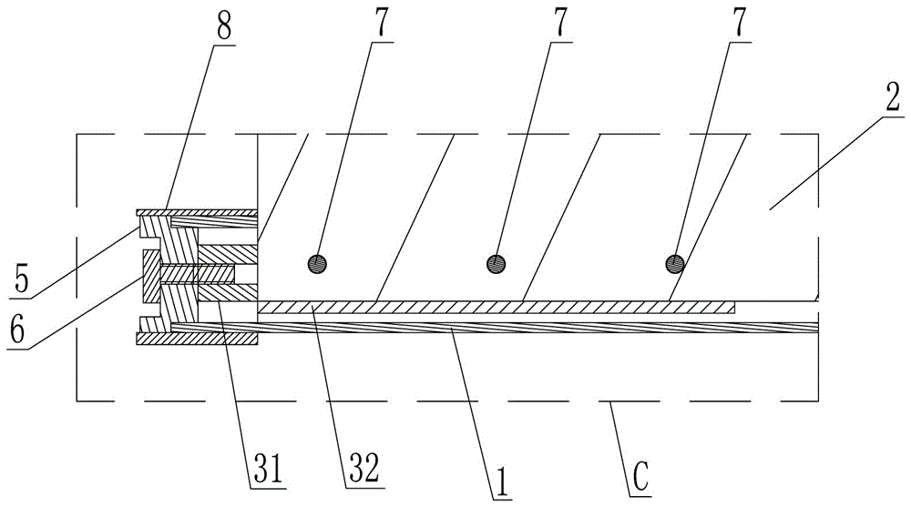
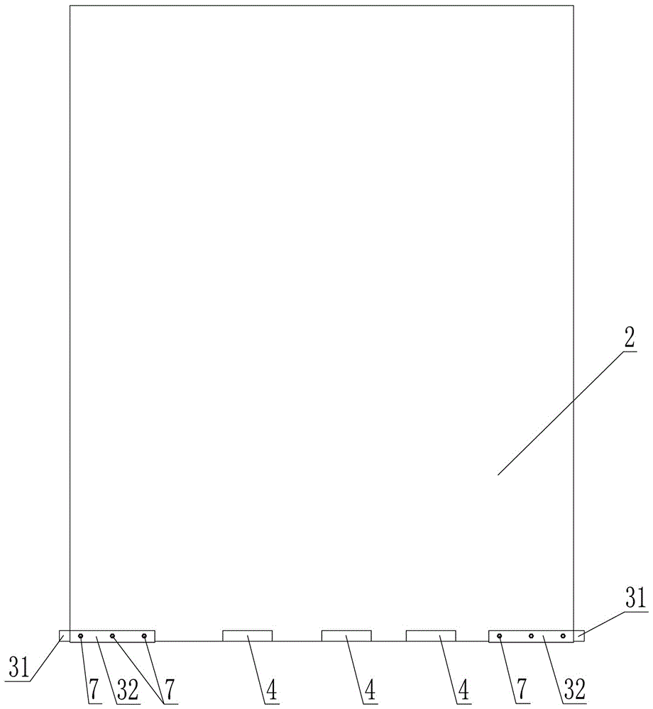
[0016] Such as figure 1 , figure 2 , image 3 , Figure 4 , Figure 5 , Image 6 As shown, the projection screen flattening device includes a hollow counterweight rod 1, and an opening that axially passes through the counterweight rod 1 and is inserted into the projection screen 2 is provided on the counterweight rod 1. The left and right ends of the bottom are respectively provided with a supporting locking block 3, and on the bottom edge of the projection screen 2 between the two supporting locking blocks 3, a number of supporting positioning pieces 4 are sequentially arranged at intervals from left to right. The upper surface of the piece 4 is located at the same horizontal position as the upper surfaces of all the supporting locking blocks 3 and jointly forms a supporting platform for hanging the counterweight rod 1, and the counterwe...


PUM


Abstract

The invention discloses a flattening device for projection screen, which comprises a hollow counter weight pull rod, an opening is arranged on the counter weight pull rod, a supporting latch segment is respectively arranged on the left end and the right end of the projection screen bottom edge, a plurality of supporting locating sheets are sequentially arranged from left to right on the projection screen bottom edge arranged between the two supporting latch segments, the upper surface of the supporting locating sheets and the upper surface of the supporting latch segment are located on the same plane to from commonly a supporting platform used for hanging and placing the counter weight pull rod, the counter weight pull rod is sequentially sleeved into all the supporting latch segment and the supporting locating sheets through the opening along the projection screen and the counter weight pull rod enables the opening edge to press down the supporting platform to hang and place on the supporting platform under the action of own gravity, plugs are respectively arranged on the left end and the right end of the counter weight pull rod, each plug is respectively locked and fixed on the ipsilateral supporting latch segment. The invention has the advantage of good flaring out effect on the projection screen.

Description

technical field [0001] The invention relates to the technical field of screens, in particular to a screen flattening device used for flattening a projected screen unfolded as a whole. Background technique [0002] The structure of the currently used projection screen is: including a projection screen storage box, a rotatable screen reel is movably supported in the projection screen storage box, the top edge of the projection screen is connected with the screen reel, and the bottom edge of the projection screen moves downward Stretch out the projection screen storage box and roll up into a roll, and a counterweight pull rod is inserted in the roll. The disadvantages of the above-mentioned projection screen are: the bottom edge of the projection screen is sewn into a roll shape by a sewing machine. On the one hand, because the sewing thread of the sewing machine cannot be kept flush during the sewing process, the counterweight pull rod is inserted into the roll. Placed in a s...

Claims


Application Information

Patent Timeline
Patent Type & Authority Applications(China)
IPC IPC(8): G03B21/58
CPCG03B21/58
Inventor 陈浩陶文华
Owner 张家港宝视特影视器材有限公司
Why Eureka
Try Eureka