
High speed train totally enclosed type permanent magnetic traction motor

A traction motor, fully enclosed technology, applied in electric components, electromechanical devices, electrical components, etc., can solve the problems of poor cooling effect of fully enclosed permanent magnet motors, inability to control the uniform temperature rise inside the motor, and avoid excessive bearing temperature. High, avoid the effect of excessive temperature rise or uneven temperature rise

Inactive Publication Date: 2017-05-24
YONGJI XINSHISU ELECTRIC EQUIP
View PDF5 Cites 8 Cited by
  • Summary
  • Abstract
  • Description
  • Claims
  • Application Information

AI Technical Summary

Problems solved by technology

[0006] The invention solves the problem that the existing fully enclosed permanent magnet motor has poor cooling effect and cannot control the uniform temperature rise inside the motor, and provides a fully enclosed permanent magnet traction motor for high-speed trains

Method used


Image

  • High speed train totally enclosed type permanent magnetic traction motor
  • High speed train totally enclosed type permanent magnetic traction motor
  • High speed train totally enclosed type permanent magnetic traction motor

Examples


Embodiment Construction

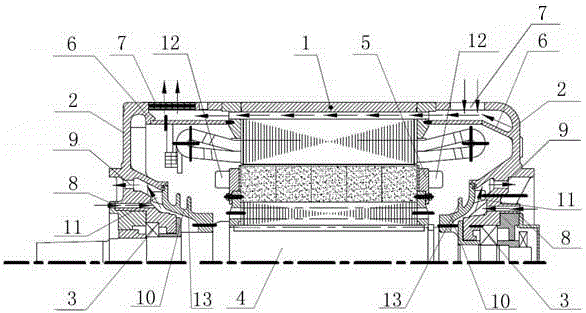
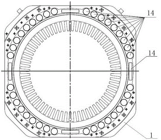
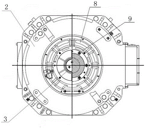
[0015] Fully enclosed permanent magnet traction motor for high-speed train, including frame 1, end cover 2, bearing 3, rotating shaft 4, permanent magnet baffle press ring 5; the frame 1 is welded by punching sheet, pressing plate, end plate, and drawing plate The pressing plate, the punching piece, and the end plate are symmetrically opened along the center of the rotating shaft 4 with multiple sets of base ventilation holes 14 axially arranged along the rotating shaft 4; the end cover 2 is provided with a ring-shaped inner wind cylinder 6, The inner air cylinder 6 is in sealed connection with the machine base 1, and the end cover 2 is provided with a plurality of end cover ventilation holes 7 distributed along the circumference of the shaft 4 in the radial direction. The end cover 2, the inner air cylinder 6, the machine The seat ventilation holes 14 are enclosed to form a machine seat cooling air path; the end cover 2 is provided with centrally symmetrically distributed beari...


PUM


Abstract

The invention relates to a permanent magnetic traction motor, to be specific, relates to a high speed train totally enclosed type permanent magnetic traction motor, which is used to solve the problems of the conventional totally enclosed type permanent magnetic motors such as poor cooling effect and inability of controlling internal even temperature rising of motor. The technical scheme provided by the invention is that a base is provided with axial air vents; end covers are provided with internal air ducts, which are connected with the base in a sealed manner, and the end covers, the internal air ducts, and the base air vents are used to form cooling wind paths in an encircled manner; the end covers are provided with cooling air inlet holes, and the outer sides are provided with cooling air outlet holes; two ends of a rotating shaft are fixedly provided with sealing discs, which are disposed between the end covers and the base, and are connected with the end covers in a sealed manner, and blades are fixedly disposed on the sealing discs between the cooling air outlet holes and the cooling air inlet holes; and self-circulation sectors are fixedly disposed on permanent magnet baffle plate clamping rings. The high speed train totally enclosed type permanent magnetic traction motor is advantageous in that 1, the three wind paths are used for the independent temperature control of the integral body of the motor; 2, the internal temperature rising of the motor is controlled in a balanced manner, and the overhigh temperature rising or the uneven temperature rising of the motor is prevented; 3, the independent cooling wind paths are designed for bearings, and then failure caused by the overhigh temperature of the bearings caused by thermal radiation and heat conduction is prevented.

Description

Technical field [0001] The invention relates to a permanent magnet traction motor, in particular to a fully enclosed permanent magnet traction motor for high-speed trains. Background technique [0002] Permanent magnet traction motor, as an important symbol of the development of high-speed trains towards high efficiency and energy saving, has always been a development trend. Permanent magnet motors are excited by permanent magnets and do not need current excitation, and rotor heating is greatly reduced; motor losses mainly come from stator windings and stator cores, making it possible for permanent magnet motors to adopt a fully enclosed structure; at the same time, to prevent dust, metal powder, and moisture , Acid, alkali and other foreign matter enter the motor, adsorb on the surface of the permanent magnet motor rotor and destroy the permanent magnet. The permanent magnet motor usually requires a fully enclosed structure. [0003] The motor adopts a fully enclosed structure, w...

Claims


Application Information

Patent Timeline
IPC IPC(8): H02K5/20H02K5/10H02K9/06
CPCH02K5/20H02K5/10H02K9/06
Inventor 贾喜勤张桂成刘荣强任延生姬春霞孙德强倪伟刘永强
Owner YONGJI XINSHISU ELECTRIC EQUIP
Learn More