A laterally movable mold changing trolley and a mold changing method thereof

A mold trolley and trolley technology, which is applied in metal processing equipment, forming tools, manufacturing tools, etc., can solve the problems of mold wear and complex transmission structure, so as to save the mold change time, stabilize the mold change process, and improve the mold change. The effect of efficiency

Active Publication Date: 2018-05-08
JIANGSU ZHISHI TECH CO LTD
View PDF8 Cites 0 Cited by
  • Summary
  • Abstract
  • Description
  • Claims
  • Application Information

AI Technical Summary

Problems solved by technology

[0005] But its disadvantage is that the transmission structure is complex
[0008] But its disadvantage is: when the mold leaves the workbench, it is forced to the mold changing trolley, which is easy to cause wear to the mold

Method used


Image

  • A laterally movable mold changing trolley and a mold changing method thereof
  • A laterally movable mold changing trolley and a mold changing method thereof

Examples


Embodiment Construction

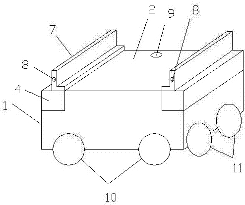
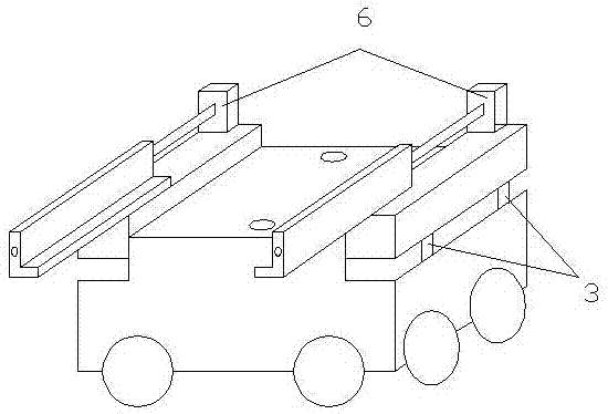
[0031] The present invention is described in further detail now in conjunction with accompanying drawing. These drawings are all simplified schematic diagrams, which only illustrate the basic structure of the present invention in a schematic manner, so they only show the configurations related to the present invention.

[0032] like figure 1 As shown, a trolley that can move laterally and change molds includes a trolley body. The trolley body includes a bearing surface and an underframe. Rail wheels are respectively arranged on both sides of the underframe along the forward direction, and the rail wheels run along guide rails. The body of the trolley is equipped with an electrical control system for controlling the mold change process. The electrical control system is equipped with a PLC controller. The two ends of the chassis along the forward direction are respectively equipped with auxiliary traverse wheels. The auxiliary traverse wheels are the same as The landing gear is...


PUM


Abstract

The invention discloses a die change trolley capable of moving transversely and a die change method thereof. The die change trolley comprises a trolley body. The trolley body comprises a bearing face and a bottom frame. An electrical control system used for controlling the die change process is arranged on the trolley body. Installation bases are arranged at the two ends of the trolley body. Lifting mechanisms are connected between the installation bases and the trolley body. Die movement arms are arranged on the installation bases. Horizontally-moving mechanisms are connected between the die movement arms and the installation bases. The cross sections of the die movement arms are each in an L shape. Shoulder steps matched with the die movement arms are arranged on the two sides of a die correspondingly. Compared with the prior art, the die change trolley has the beneficial effects that the die is elevated through the lifting mechanisms first and is then moved onto the trolley through the horizontally-moving mechanisms, the bottom face of the die does not rub a working table or the trolley in the whole process, the die change process is stable, the die change time is saved, and the die change efficiency is improved.

Description

technical field [0001] The invention belongs to supporting equipment for mold changing operations of stamping machines, and relates to a laterally movable mold changing trolley and a mold changing method thereof. Background technique [0002] In the current plastics industry, when changing molds, only cranes and manpower can be used to change molds. When the crane is changing the mould, it is prone to illegal operations such as crooked pulling and slanting, and the wire rope is also prone to damage the machine tool equipment during the pulling process. On the other hand, because the pulling distance is difficult to control, the operator operates completely by his own feeling, which is very easy to cause accidents where the mold slips to the ground and hurts people due to improper force. In addition, moving large molds manually is time-consuming and labor-intensive. [0003] Chinese patent, application number 201220164757.0, discloses a laterally movable mold changing troll...

Claims


Application Information

Patent Timeline
Patent Type & Authority Patents(China)
IPC IPC(8): B21D37/14
CPCB21D37/147
Inventor 陆辰钊范磊
Owner JIANGSU ZHISHI TECH CO LTD
Why Eureka
Try Eureka