

Quick hoisting type mold changing trolley and mold changing method thereof
A mold trolley and trolley technology, which is applied in metal processing equipment, forming tools, manufacturing tools, etc., can solve the problems of mold wear and complex transmission structure, so as to save the mold change time, stabilize the mold change process, and improve the mold change. The effect of efficiency
- Summary
- Abstract
- Description
- Claims
- Application Information
AI Technical Summary
Problems solved by technology
Method used
Image

Examples
Embodiment Construction
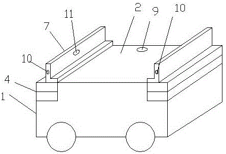
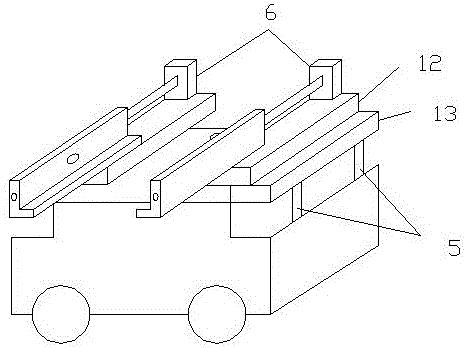
[0032] The present invention is described in further detail now in conjunction with accompanying drawing. These drawings are all simplified schematic diagrams, which only illustrate the basic structure of the present invention in a schematic manner, so they only show the configurations related to the present invention.
[0033] Such as figure 1 As shown, a quick-lifting mold changing trolley includes a trolley body, the trolley body includes a bearing surface and an underframe, the underframe is provided with wheels, the wheels run along guide rails, and the trolley body is equipped with For the electrical control system that controls the mold change process, there is a PLC controller in the electrical control system, and the two ends of the trolley body along its moving direction are respectively movably connected to a mounting seat, and there is a lifting device between the mounting seat and the trolley body. mechanism, the lifting mechanism drives the mounting seat to lift...
PUM
 Abstract
Description
Claims
Application Information