
Grinding device

A technology of grinding and mounting discs, applied in the direction of grinding workpiece supports, grinding/polishing equipment, grinding machines, etc., can solve problems such as the deviation of the engine rotation center, and achieve the effect of avoiding the positioning error of the fixture

Active Publication Date: 2018-11-27
CHINA HANGFA SOUTH IND CO LTD
View PDF6 Cites 0 Cited by
  • Summary
  • Abstract
  • Description
  • Claims
  • Application Information

AI Technical Summary

Problems solved by technology

[0005] The invention provides a grinding device to solve the technical problem that the blade tip arc of the existing grinder fixture deviates from the engine rotation center

Method used


Image

  • Grinding device
  • Grinding device
  • Grinding device

Examples


Embodiment Construction

[0034] It should be noted that, in the case of no conflict, the embodiments in the present application and the features in the embodiments can be combined with each other. The present invention will be described in detail below with reference to the accompanying drawings and examples.

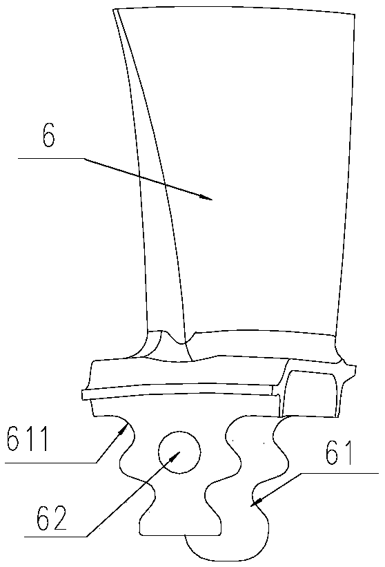
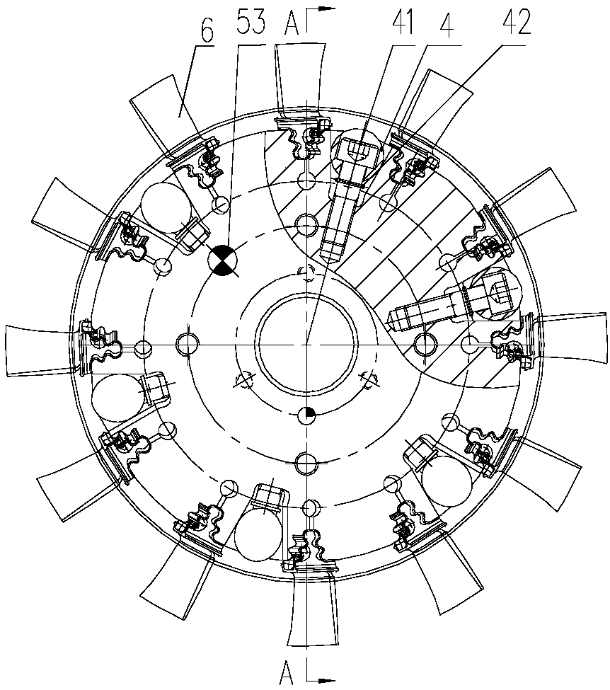
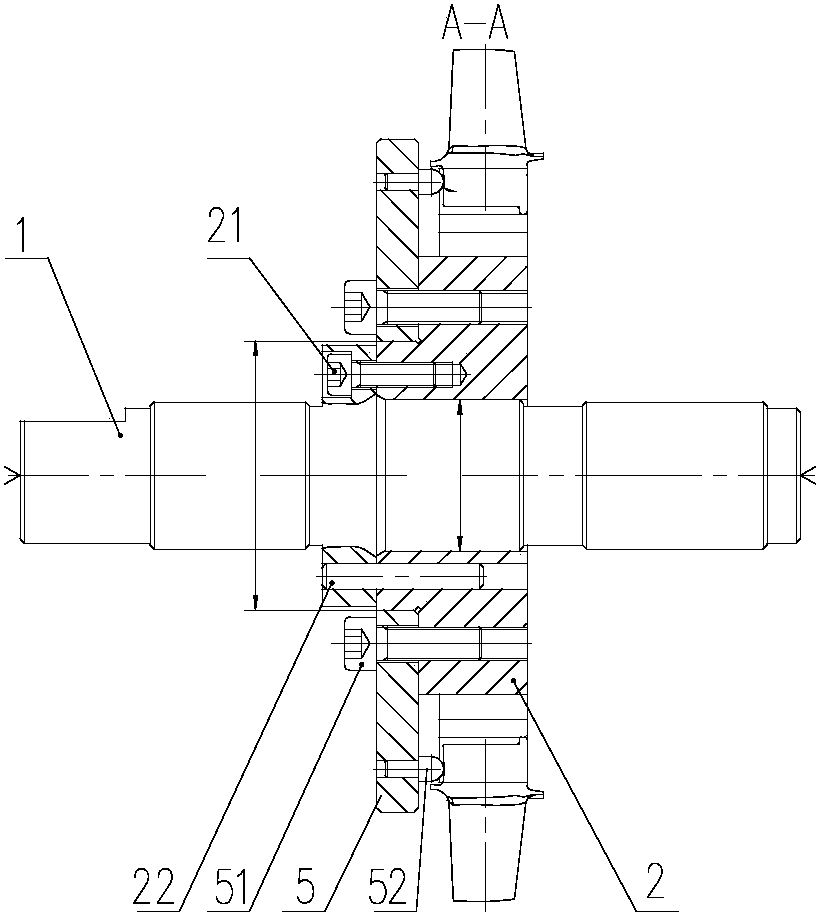
[0035] refer to Figure 1 to Figure 4 , the preferred embodiment of the present invention provides a grinding device for fixing the blades of the engine, the grinding device includes a central shaft 1 concentric with the engine and a mounting disc 2 for fixing the blades 6 which is clearance fit with the central shaft 1 ;

[0036] The mounting plate 2 includes a plurality of tenon grooves 31 arranged along the circumferential direction for fixing the tenon 61 of the blade. 312, between the adjacent pressing sides 312, there is a pressing part 4 for pressing two adjacent pressing sides 312, so that the pressing sides 312 clamp the tenon 61 of the blade, so as to ensure that the blade 6 does no...


PUM


Abstract

The invention discloses a grinding device for fixing an engine blade. The grinding device comprises a central shaft which is concentric with the engine and an installing plate matched with the clearance of the central shaft for fixing the blade. The installing plate comprises a plurality of mortises for fixing blade rabbets and installed along the peripheral direction. Through a positioning edge installed on the mortises and matched with the blade rabbets and a pressing edge for pressing the blade rabbets, the blade rabbets are pressed by a pressing component. In the pressing process of the pressing component, the blade rabbets are tightly adhered to the positioning edge, only the pressing edge is deviated, and the blade is not relatively moved, so that the blade is not deviated from the center of the installing plate. The clamp positioning error generated in the process of grinding the outer circle of the blade can be avoided, and the technical problem that the rotation center is deviated in the machining process of the blade tip arc and the engine by using the current grinding clamp can be solved.

Description

technical field [0001] The invention relates to the field of aeroengines, in particular to a grinding device for engine blades. Background technique [0002] Before the engine gas turbine rotor is assembled to the engine, the entire blade tip needs to be ground. When grinding the blade tip, the blade tenon needs to be clamped. The original grinder fixture is designed according to the tenon and groove profile of the turbine disk. In order to facilitate the blade tenon to be placed in the fixture tenon groove, the unilateral gap between the tenon and the blade tenon of the fixture is about 0.1mm. After the tenon is clamped, the blade deviates from the center of the fixture by about 0.1mm , after the blade is ground, the blade tip arc deviates from the theoretical center (engine rotation center) by 0.1mm, which affects the machining accuracy of the blade. [0003] In addition, when grinding and processing the blade tip, the original axial limit is positioned by the end face of...

Claims


Application Information

Patent Timeline
Patent Type & Authority Patents(China)
IPC IPC(8): B24B41/06B24B19/14
CPCB24B19/14B24B41/06
Inventor 李展前陈鹰卢美霖
Owner CHINA HANGFA SOUTH IND CO LTD
Learn More