
Prefabricated component, connecting structure of prefabricated component and bearing platform and machining method of prefabricated component

A prefabricated component and screw connection technology, applied in the direction of structural elements, building components, manufacturing tools, etc., can solve the problems of cumbersome operation of underground prefabricated components and bearing platforms, complicated production process, etc., to save construction period, reduce environmental pollution, structure Simple and clever design

Pending Publication Date: 2020-06-30
江苏诚意桩业科技发展有限公司 +1
View PDF0 Cites 1 Cited by
  • Summary
  • Abstract
  • Description
  • Claims
  • Application Information

AI Technical Summary

Problems solved by technology

At present, the product technology of these piles has been innovated in the production process, production equipment, and production line layout, but the production process is complicated, and the upper end plate or spring clip or sleeve is connected with the component through the anchor reinforcement. There is a deviation in the axial steel bar itself, which makes the operation cumbersome when connecting the underground prefabricated components with the cap

Method used


Image

  • Prefabricated component, connecting structure of prefabricated component and bearing platform and machining method of prefabricated component
  • Prefabricated component, connecting structure of prefabricated component and bearing platform and machining method of prefabricated component
  • Prefabricated component, connecting structure of prefabricated component and bearing platform and machining method of prefabricated component

Examples


Embodiment Construction

[0050] The present invention will be described below according to the embodiments shown in the accompanying drawings. It can be thought that embodiment disclosed this time is an illustration in every point, and is not restrictive. The scope of the present invention is not limited by the description of the following embodiments but only by the scope of the claims, and includes the same meaning as the scope of the claims and all modifications within the scope of the claims.

[0051] The prefabricated component, the connection structure between the prefabricated component and the platform and the processing method of the prefabricated component of the present invention will be described below in conjunction with specific embodiments.

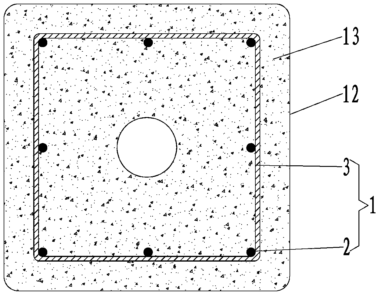
[0052] Such as figure 1 Shown is a top view sectional structural schematic diagram of the prefabricated member embodiment 1 of the present invention, including a reinforcement cage 1, which is welded by a plurality of longitudinal prestressed main...


PUM


Abstract

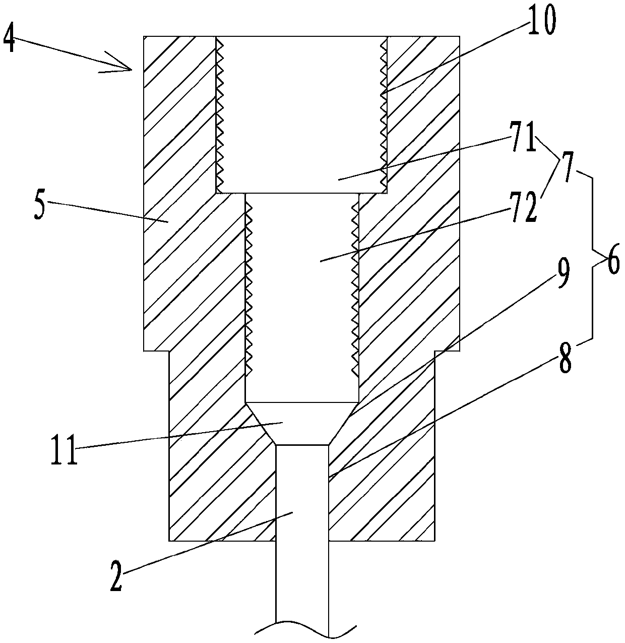
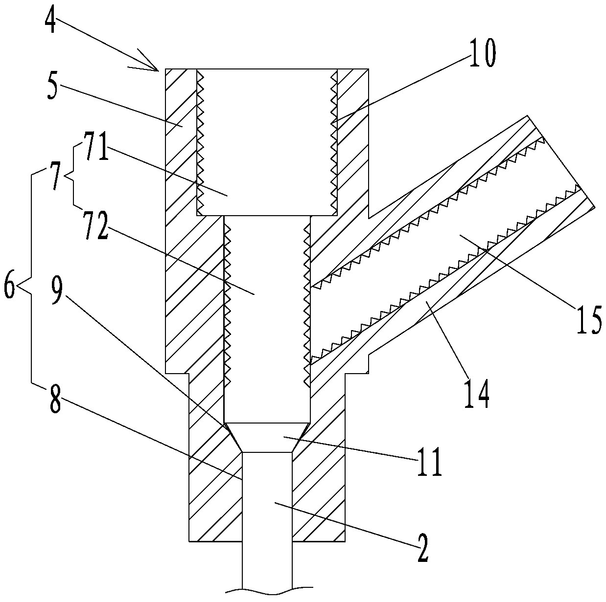
The invention discloses a prefabricated component, a connecting structure of the prefabricated component and a bearing platform and a machining method of the prefabricated component. The prefabricatedcomponent comprises a reinforcement cage, wherein the upper ends of longitudinal main ribs of the reinforcement cage are correspondingly connected with sleeves, each sleeve comprises a sleeve body, the center of each sleeve body is provided with a through hole, each through hole comprises a stepped first hole, a second hole and an upset head hole located between the first hole and the second hole, the aperture of the upper portion of each first hole is larger than that of the lower hole of each first hole, the aperture of each first hole is larger than that of each second hole, the inner wallof each first hole is at least partially provided with a first internal thread, and upset heads of the upper end of the main ribs are snapped in the upset head holes, and the main ribs penetrate through the second holes downwards. According to the prefabricated component, the connection operation of the sleeves of the prefabricated component and the reinforcement cage is convenient, the machiningprocess is environment-friendly, the connecting structure of the prefabricated component and the bearing platform is convenient to connect and operate, and the non-deviation of the connection betweenthe main ribs of the reinforcement cage and anchoring steel bars on the bearing platform can be ensured.

Description

technical field [0001] The invention relates to the technical field of building prefabricated component base connectors, in particular to a prefabricated component, a connection structure between the prefabricated component and a platform, and a processing method for the prefabricated component. Background technique [0002] At present, municipal, water conservancy, civil, railway, electric power and other infrastructure constructions require a large number of prefabricated concrete components. The Ministry of Housing and Urban-Rural Integration, the Ministry of Water Resources and other departments clearly put forward the requirements of standardization, informatization, dataization, prefabrication and other requirements for the use of prefabricated components in engineering construction, and put forward a series of requirements for green products and other solutions. [0003] At present, there are many prefabricated products in the field of construction, such as prefabrica...

Claims


Application Information

Patent Timeline
Patent Type & Authority Applications(China)
IPC IPC(8): E04B1/00E04B1/38E04C5/16B28B23/02B28B23/04B28B1/20B28B11/24
CPCE04B1/00E04B1/38E04C5/16B28B23/024B28B23/043B28B1/20B28B11/245
Inventor 陈芳斌黄玉楼曹虎陈鹏武鹏飞
Owner 江苏诚意桩业科技发展有限公司
Learn More