
A rubber punching station in an automatic punching and cutting stacked sheet swing device

An automatic punching and punching technology, applied in metal processing and other directions, to achieve the effect of improving practical performance

Active Publication Date: 2018-10-30
SUZHOUSCON AUTOMATION TECH
View PDF6 Cites 0 Cited by
  • Summary
  • Abstract
  • Description
  • Claims
  • Application Information

AI Technical Summary

Problems solved by technology

The two jaws continue to step and drive the rubber to move

Method used


Image

  • A rubber punching station in an automatic punching and cutting stacked sheet swing device
  • A rubber punching station in an automatic punching and cutting stacked sheet swing device
  • A rubber punching station in an automatic punching and cutting stacked sheet swing device

Examples


Embodiment Construction

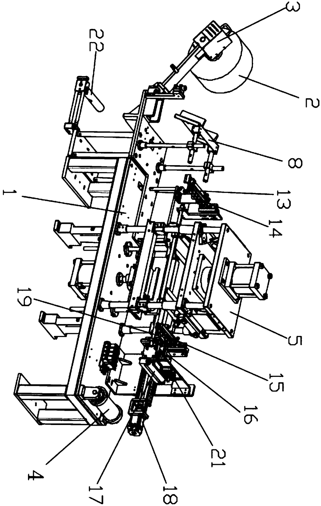
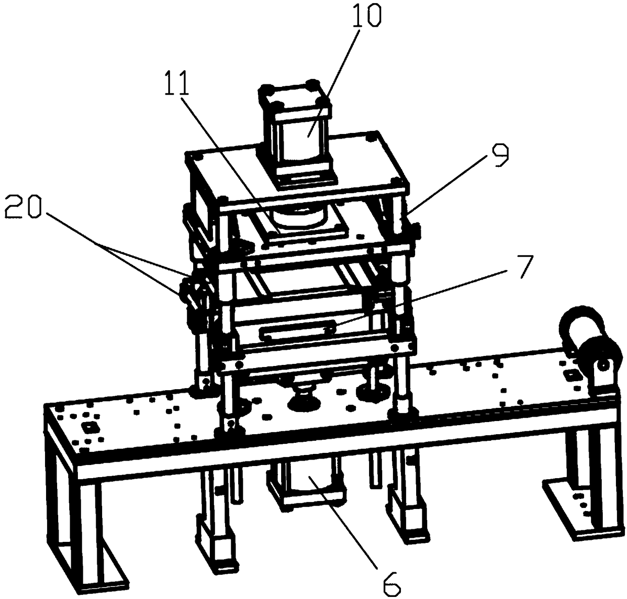
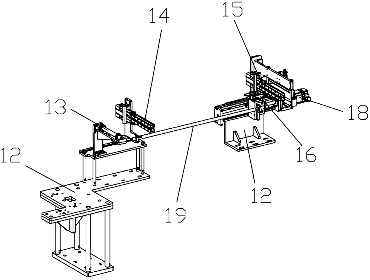
[0022] Such as figure 1 with image 3 The rubber blanking station in an automatic punching and stacking sheet swing device shown includes a bracket 1, a feeding roller, a feeding slide 8, a feeding roller 4, a cutting die 5, a conveying device and a lifting Cylinder 6, the discharge roller is connected to the discharge motor 3, the discharge motor 3 is connected to one end of the bracket 1 through the mounting bracket, and the feeding slide 8 is installed on the same end of the discharge roller Bracket 1, the described blanking roller 4 is installed on the other end of the bracket 1, and the described cutting mold 5 is installed on the bracket 1, and the described cutting mold 5 is located between the feeding slide 8 and the blanking roller 4 Between, the conveying device is installed on the rubber blanking support 1 between the loading slide 8 and the unloading roller 4, the conveying device passes through the cutting die 5, and the jacking cylinder 6 is installed At the bo...


PUM


Abstract

The patent of the present invention relates to a rubber punching station in automatic punching and lamination stacking equipment, including a bracket, a feeding roller, a feeding slide, a feeding roller, a cutting die, a conveying device and a jacking cylinder. The discharge roller is connected to the discharge motor, the discharge motor is connected to one end of the bracket through the mounting bracket, the feeding slide plate is installed on the bracket at the same end of the discharge roller, and the discharge roller Installed on the other end of the bracket, the cutting die is installed on the bracket, the cutting die is located between the feeding slide and the unloading roller, and the conveying device is installed between the feeding slide and the unloading roller On the rubber blanking support between the two, the conveying device passes through the cutting mold, the jacking cylinder is installed at the bottom of the bracket directly below the cutting mold, and the jacking cylinder passes through the bracket and The jacking fixtures are connected. The design has the advantages of simple structure, easy manufacture, practicality and high efficiency.

Description

technical field [0001] The patent of the present invention relates to the field of tire patch punching and forming, especially a rubber punching station in an automatic punching and stacking sheet swinging device. Background technique [0002] At present, there is no automatic die-cutting and stacking equipment in the field of tire patch manufacturing in China. It mainly relies on manual stacking of punched single-layer tire supplements and then manually stacks them. The production capacity and quality cannot be guaranteed, especially for tire supplements. In the process of sheet punching, the existing punching station has great limitations, so in order to improve the punching efficiency of the tire patch, a rubber punching station in the automatic punching and stacking sheet swing equipment is designed. Standing is even more important. Contents of the invention [0003] The purpose of the present invention is to design a rubber punching station in the automatic punching ...

Claims


Application Information

Patent Timeline
Patent Type & Authority Patents(China)
IPC IPC(8): B26F1/40B26F1/44B26D7/06B26D7/00B26D7/32
CPCB26D7/00B26D7/06B26D7/32B26D2007/0012B26F1/3866B26F1/40B26F1/44
Inventor 曾航张荣
Owner SUZHOUSCON AUTOMATION TECH
Learn More