
Titanium alloy skeleton skin structure welding device

A welding device and titanium alloy technology, applied in the direction of welding equipment, auxiliary equipment, auxiliary welding equipment, etc., can solve the problems of affecting the quality of the weld, being invisible, and wasting a lot of time, so as to ensure the quality of the weld and control the welding deformation. Effect

Active Publication Date: 2018-09-25
BEIJING HANGXING MACHINERY MFG CO LTD
View PDF7 Cites 0 Cited by
  • Summary
  • Abstract
  • Description
  • Claims
  • Application Information

AI Technical Summary

Problems solved by technology

The difficulty in the welding of this type of parts is that the skin surface is a space aerodynamic shape, the size is large, and it is difficult to control the welding deformation; the cold forming precision of the titanium alloy skin is low, and it cannot fit closely with the skeleton; the skeleton size is small Long and narrow, the weld positions are distributed on the entire space surface, and the number of intermittent welds is as many as several hundred. If the weld position is slightly deviated, it will penetrate into the lower skin
[0003] The existing welding device uses a simple pressure plate or a bow clamp to clamp the skin and the skeleton at a local position outside the welded part, which cannot effectively control the overall welding deformation of the welded part, and the profile accuracy after welding is above 0.5mm. It exceeds the range required by the product; the skin at some weld positions cannot be closely attached to the skeleton, often exceeding the gap value required by high-energy beam welding, which affects the quality of the weld; moreover, such devices need to waste a lot of time to determine the weld position, and The slender skeleton is under the skin and cannot be seen, and the deviation of the weld position is more than 1mm

Method used


Image

  • Titanium alloy skeleton skin structure welding device
  • Titanium alloy skeleton skin structure welding device
  • Titanium alloy skeleton skin structure welding device

Examples


Embodiment Construction

[0021] Embodiments of the present invention will be described in further detail below in conjunction with the accompanying drawings.

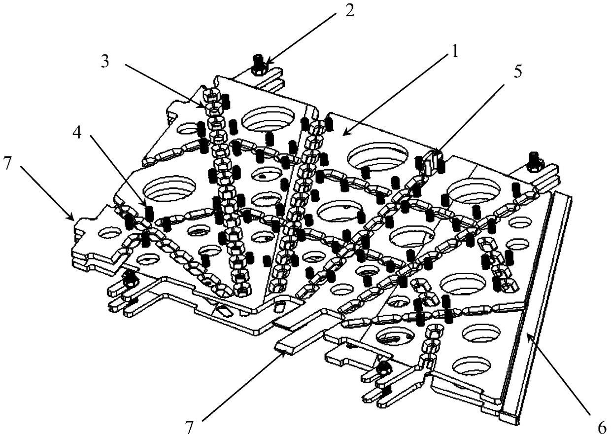
[0022] like figure 1 A welding device for a titanium alloy skeleton skin structure is shown, the device includes a profile pressing plate 1, a clamping member 2, a pressing piece 4, a marking block 5, and a plug block 6; two profile pressing plates are in four Under the action of the clamping member 2, the outer skin of the welded part is pressed and fixed; the pressing part 4 is installed on the profile pressing plate 1, and is used to clamp the skin and skeleton of the welded part; the plug 6 is placed on the welded part The upper and lower skin edges of the parts are used to prevent the edge skin welding deformation.

[0023] There are light-removing holes on the profile pressing plate 1, the inner profile of the profile pressing plate 1 adapts or coincides with the shape of the welded part, and the positioning datum 7 is set in two directi...


PUM


Abstract

The invention discloses a welding device for a titanium alloy skin structural member for a framework. The welding device mainly comprises a molded surface pressing plate, clamping components, pressing parts, line marking blocks and a plug block, wherein welding grooves are formed in the molded surface pressing plate having welding positioning references; the molded surface pressing plate presses and fixes an outer skin of a to-be-welded part under the effect of the clamping components; the plug block is disposed at the edge of the skin for preventing welding deformation; the pressing parts are arranged near welding lines and are used for performing multi-point fixation for the titanium alloy skin so as to guarantee effective and tight fit of the skin and the framework and to guarantee the precision and the quality of the welding lines. The welding device is made of austenitic stainless steel, so that the welding device is suitable for different high-energy beam welding methods. The contour precision of the part reaches 0.1-0.2 mm. By the positioning references and the welding grooves, time for determining welding line positions is largely shortened and the welding efficiency is improved by more than two times. The welding device is suitable for the welding of large-size titanium alloy skin structural members for frameworks.

Description

technical field [0001] The invention relates to a welding device, in particular to a welding device for a titanium alloy skeleton skin structure. It belongs to the field of process equipment design and is suitable for high-energy beam welding forming of titanium alloy skeleton skin parts for aerospace. Background technique [0002] Titanium alloy skeleton-skin welded structural parts are important parts of some aerospace products, and are often welded by high-energy beam welding. The difficulty in the welding of this type of parts is that the skin surface is a space aerodynamic shape, the size is large, and it is difficult to control the welding deformation; the cold forming precision of the titanium alloy skin is low, and it cannot fit closely with the skeleton; the skeleton size is small The length is narrow and small, and the positions of the welds are distributed on the entire surface of the space. The number of intermittent welds is as many as several hundred. If the p...

Claims


Application Information

Patent Timeline
Patent Type & Authority Patents(China)
IPC IPC(8): B23K37/04
CPCB23K37/0435
Inventor 张珊珊秦英步贤政李妍华刘国柱
Owner BEIJING HANGXING MACHINERY MFG CO LTD
Learn More