Grouting shrinkage compensation method

A compensation method and grouting port technology, applied to structural elements, building components, building reinforcements, etc., can solve problems such as grouting difficulties, and achieve the effects of simple grouting process control, reduced process requirements, and improved reliability

Active Publication Date: 2017-05-31
北京汇丰鸿信科技有限公司 +1
View PDF5 Cites 15 Cited by
  • Summary
  • Abstract
  • Description
  • Claims
  • Application Information

AI Technical Summary

Problems solved by technology

Even if it is determined that the grout is not full, it is very difficult to replenish the g

Method used


Image

  • Grouting shrinkage compensation method
  • Grouting shrinkage compensation method
  • Grouting shrinkage compensation method

Examples


Embodiment 1

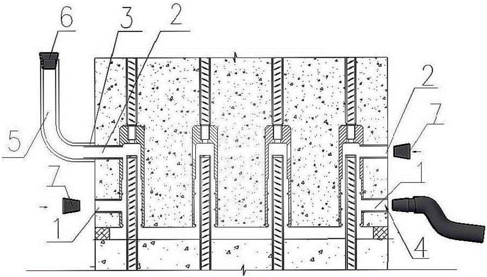
[0033] Such as Figure 1-2 As shown, the grouting shrinkage compensation method of this embodiment is used to compensate for the shrinkage of the grout volume caused by exhaust and water absorption when the vertical connection of the prefabricated concrete structure is grouted by the Unicom cavity, and mainly includes the following steps:

[0034] (1) When preparing for grouting, choose to determine a grouting port 1 as the grouting port 4, and one or more grouting ports 2 to install feeding risers 5. When the size of the Unicom cavity is small, only one riser can be used , it is preferentially installed on the slurry discharge port farthest from the filling port; when the size of the communication cavity is large, two or more risers can be installed and evenly distributed in each position of the communication cavity. Install the riser installation joint 3 on the discharge port where the feeding riser is installed. The slurry discharge pipe reserved outside the wall can be us...

Embodiment 2

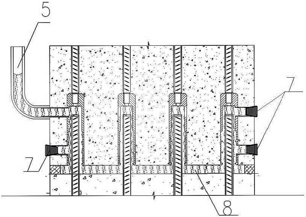
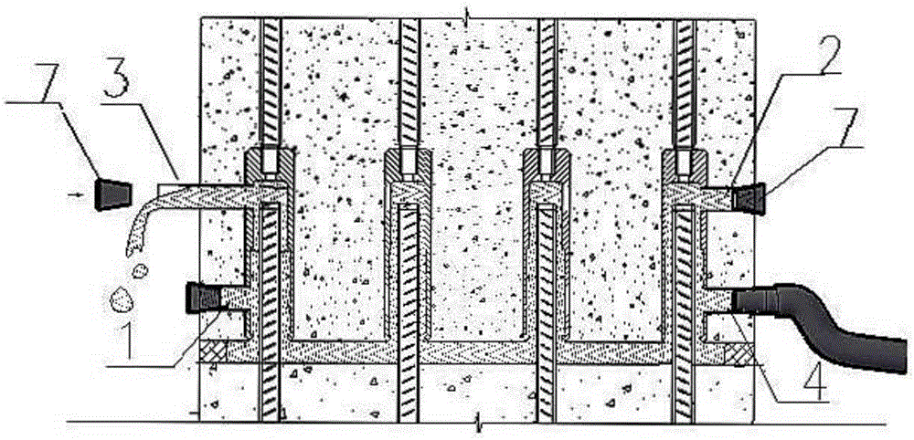
[0039] Such as Figure 3-Figure 5 As shown, the grouting shrinkage compensation method of this embodiment is used to compensate for the shrinkage of the grout volume caused by exhaust and water absorption when the vertical connection of the prefabricated concrete structure is grouted by the Unicom cavity, and mainly includes the following steps:

[0040] (1) Same as embodiment one step (1).

[0041] (2) Use the pressure grouting method to inject the grouting material from the filling port 4. During the grouting process, when the grout flows out from the grouting port 1 or the grouting port 2, immediately block it with the grouting port and the grouting port plug 7 until all grouting After the grout is discharged from the port (except the pouring port) and the grouting port, the grouting is suspended.

[0042](3) Remove the plug 7 on the riser installation joint 3, install the feeding riser 5 on the installation joint 3, and continue grouting until the slurry in the riser 5 ex...


PUM


Abstract

The invention discloses a grouting shrinkage compensation method for grouting connection of vertical reinforcing steel bars when prefabricated concrete components are grouted through communicated gravities. The grouting shrinkage compensation method comprises the following steps: setting a grouting feeding head in the appropriate position of a communicated cavity, and filling the communicated cavity with grouting slurry and filling the grouting feeding head as well when grouting is implemented, wherein the upper end of the grouting feeding head is higher than a highest point of a grouting cavity. Because of the gravity function of the slurry in the grouting feeding head, grouting slurry shrinkage caused by reasons such as density, water loss and air exhaust in the curing process of the grouting slurry can be compensated, and the situation that the liquid level of the grouting slurry inside a sleeve is lowered and the sleeve is not fully grouted can be prevented. By adopting the grouting shrinkage compensation method, full grouting can be ensured, and meanwhile a reliable criterion is provided for grouting connection quality inspection.

Description

technical field [0001] The invention relates to the technical field of connection construction of prefabricated concrete components, in particular to a construction method for vertical reinforcement grouting connection of an assembled concrete structure. Background technique [0002] The pressure grouting method of the connecting cavity is the main method of the vertical steel grouting connection construction of the prefabricated concrete structure at present. After the prefabricated components are installed in place, seal the horizontal joints below them with sealing materials or special devices, use the horizontal joints as the connecting cavity, and grout inward from a grouting joint or a grouting opening reserved for a horizontal joint to fill the entire joint at one time cavities, including horizontal joints and cavities inside all connecting joints, when all other grouting ports and grouting ports have grout flowing out, all grouting ports and grouting ports are blocke...

Claims


Application Information

Patent Timeline
IPC IPC(8): E04C5/16
CPCE04C5/162
Inventor 狄姝敏
Owner 北京汇丰鸿信科技有限公司
Why Eureka
Try Eureka