
Control Method of Constant Pressure Air Supply of Multistage Centrifugal Air Compressor

An air compressor and control method technology, applied in the direction of engine control, pump control, mechanical equipment, etc., can solve problems such as surge shutdown, overcurrent shutdown, and constant air supply on the gas site, and achieve the effect of stabilizing working pressure

Active Publication Date: 2018-01-23
CHONGQING JIANGJIN SHIPBUILDING IND
View PDF5 Cites 0 Cited by
  • Summary
  • Abstract
  • Description
  • Claims
  • Application Information

AI Technical Summary

Problems solved by technology

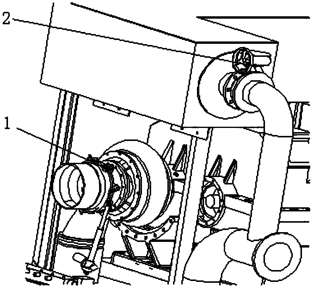
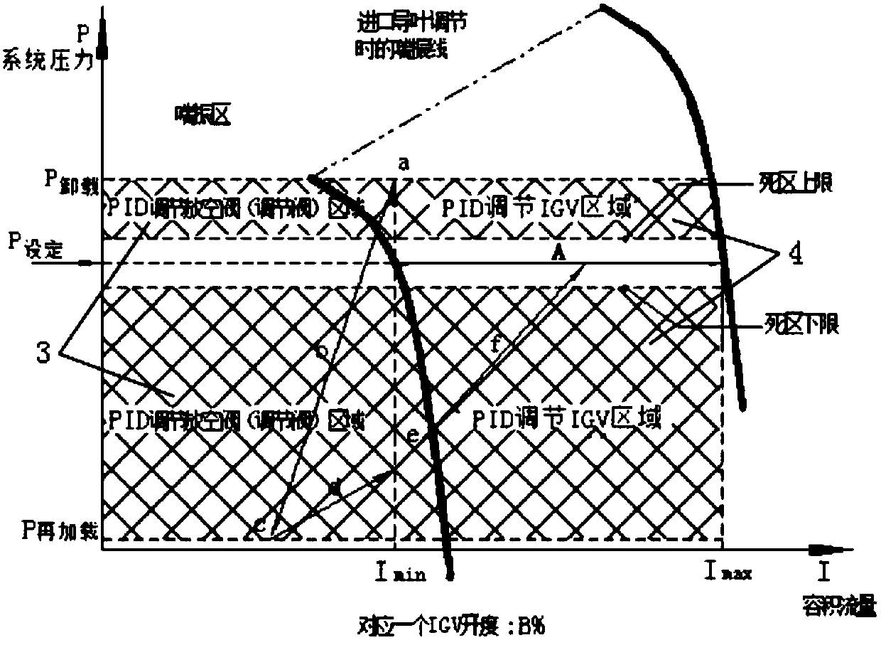
[0003] The purpose of the present invention is to provide a multi-stage centrifugal pump to solve the problems in the prior art that it is impossible to provide constant gas supply to the site of gas consumption, the control of constant pressure gas supply is difficult, and overcurrent shutdown and surge shutdown often occur during the control process. A control method for constant pressure air supply of a type compressor. This method determines the control and adjustment area map of the compressor according to the design parameters of the compressor and experimental data, and then judges which adjustment area is currently in according to the current pressure value and current value, and adjusts the inlet through PID. The opening of guide vane IGV or vent valve BOV achieves the purpose of constant pressure air supply

Method used


Image

  • Control Method of Constant Pressure Air Supply of Multistage Centrifugal Air Compressor
  • Control Method of Constant Pressure Air Supply of Multistage Centrifugal Air Compressor
  • Control Method of Constant Pressure Air Supply of Multistage Centrifugal Air Compressor

Examples


Embodiment Construction

[0027] The present invention will be described in further detail below in conjunction with the embodiments and accompanying drawings.

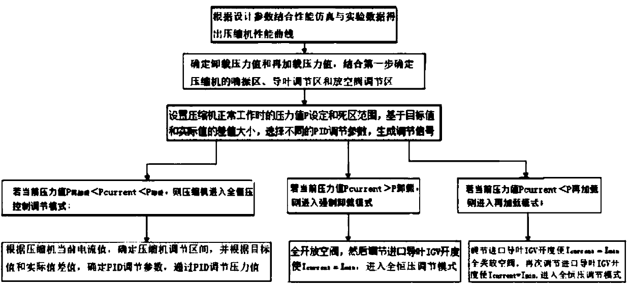
[0028] see figure 1 As shown, the control method for constant-pressure air supply of a multi-stage centrifugal air compressor is characterized in that it includes the following steps:

[0029] The first step is to obtain the performance curve of the multi-stage compressor according to the design parameters of the multi-stage compressor combined with performance simulation and experimental data;

[0030] The second step is to determine the unloading pressure value and reloading pressure value, combined with the first step to determine the surge area, guide vane adjustment area and vent valve adjustment area of ​​the multi-stage compressor;

[0031] The third step is to set the set pressure value P when the compressor works normally. 设定 and dead zone range, based on the difference between the target value and the actual value, select different...


PUM


Abstract

The invention discloses a constant pressure air feeding control method for a multistage centrifugal air compressor. The method comprises the following steps: 1, combining performance simulation and experimental data to obtain a compressor performance curve according to design parameters; 2, determining an unloading pressure value and a reloading pressure value, and combining the first step to determine a surge area, a guide vane regulating area and a vent valve regulating area; 3, arranging P setting and dead zone range during normal operation, and generating a regulating signal; 4, entering a full constant pressure control regulating mode if Pcurrent is more than Preloading and less than Punloading, and entering a step 5; entering a forced unloading mode and entering a step 6 if Pcurrent is more than Punloading; entering a reloading mode and entering a step 7 if Pcurrent is less than Preloading; 5, determining a regulating interval, determining a PID (Proportion Integration Differentiation) regulating parameter, and regulating the pressure value through PID; 6, totally opening the vent valve, regulating IGV (Inlet Guide Vane) opening to enable Icurrent to be equal to Imin, and entering a full constant pressure regulating mode; and 7, regulating the IGV opening to enable Icurrent to be equal to Imin, totally opening the vent valve, regulating the IGV opening again to enable Icurrent to be equal to Imin, and entering the full constant pressure regulating mode.

Description

technical field [0001] The invention relates to the technical field of control of centrifugal compressors, in particular to a control method for constant-pressure air supply of multistage centrifugal compressors. Background technique [0002] Multi-stage centrifugal compressors are widely used in petrochemical, air separation and pharmaceutical engineering to provide industrial gases. In many applications, constant pressure gas supply is required. In industrial sites, due to process and other influences, As a result, the gas consumption often changes; in addition, the length of the pipeline, the size of the gas storage tank and other factors also cause the speed of the pressure change of the compressor to be very different due to the change of the gas consumption in different occasions. It brings great difficulty to the constant pressure control of the multi-stage centrifugal compressor. In addition, during the control process, the switching speed of the guide vane and the v...

Claims


Application Information

Patent Timeline
Patent Type & Authority Patents(China)
IPC IPC(8): F04D27/00
CPCF04D27/002F04D27/007F04D27/009F04D27/0207F04D27/0223F04D27/0246F04D27/0284F05D2270/706
Inventor 侯春峰雷娜李新宇谢小华曾勇
Owner CHONGQING JIANGJIN SHIPBUILDING IND
Learn More