
A construction machinery hydraulic oil return control circuit and its control method

A technology for oil return control and construction machinery, applied in mechanical equipment, servo meter circuits, fluid pressure actuating devices, etc., can solve the problems of high back pressure, affecting the temperature rise of the hydraulic system, energy loss, etc., to achieve reasonable energy flow, Increase oil return resistance and save energy

Active Publication Date: 2018-08-14
内蒙古山河巨鼎矿用机械制造有限责任公司
View PDF7 Cites 0 Cited by
  • Summary
  • Abstract
  • Description
  • Claims
  • Application Information

AI Technical Summary

Problems solved by technology

[0002] In the hydraulic system of construction machinery, especially in hydraulic excavators, in order to prevent the suction of the rotary motor of the hydraulic actuator, it is necessary to add the first back pressure valve on the oil return line of the hydraulic system, so as to effectively protect the rotary motor, but due to If the pressure of the first back pressure valve is too high, the back pressure of the whole system will be too high, so the second back pressure valve is added to solve the problem that the back pressure value exceeds the hydraulic system’s tolerance when the return oil volume is large, and The setting value of the back pressure valve is generally above 2.5bar, the average working pressure in actual work reaches above 4.0bar, and the peak value reaches about 7.0bar, which leads to an increase in the pressure of the entire system and unnecessary power loss
[0003] At the same time, when the excavator is in winter or in extremely cold weather, the low hydraulic oil temperature increases the preheating process. At the same time, the oil in the hydraulic system still needs to pass through the radiator to dissipate heat, which also affects the entire hydraulic system. temperature rise, resulting in unnecessary energy loss

Method used


Image

  • A construction machinery hydraulic oil return control circuit and its control method

Examples


Embodiment Construction

[0022] The present invention will be further described below in conjunction with accompanying drawing and embodiment:

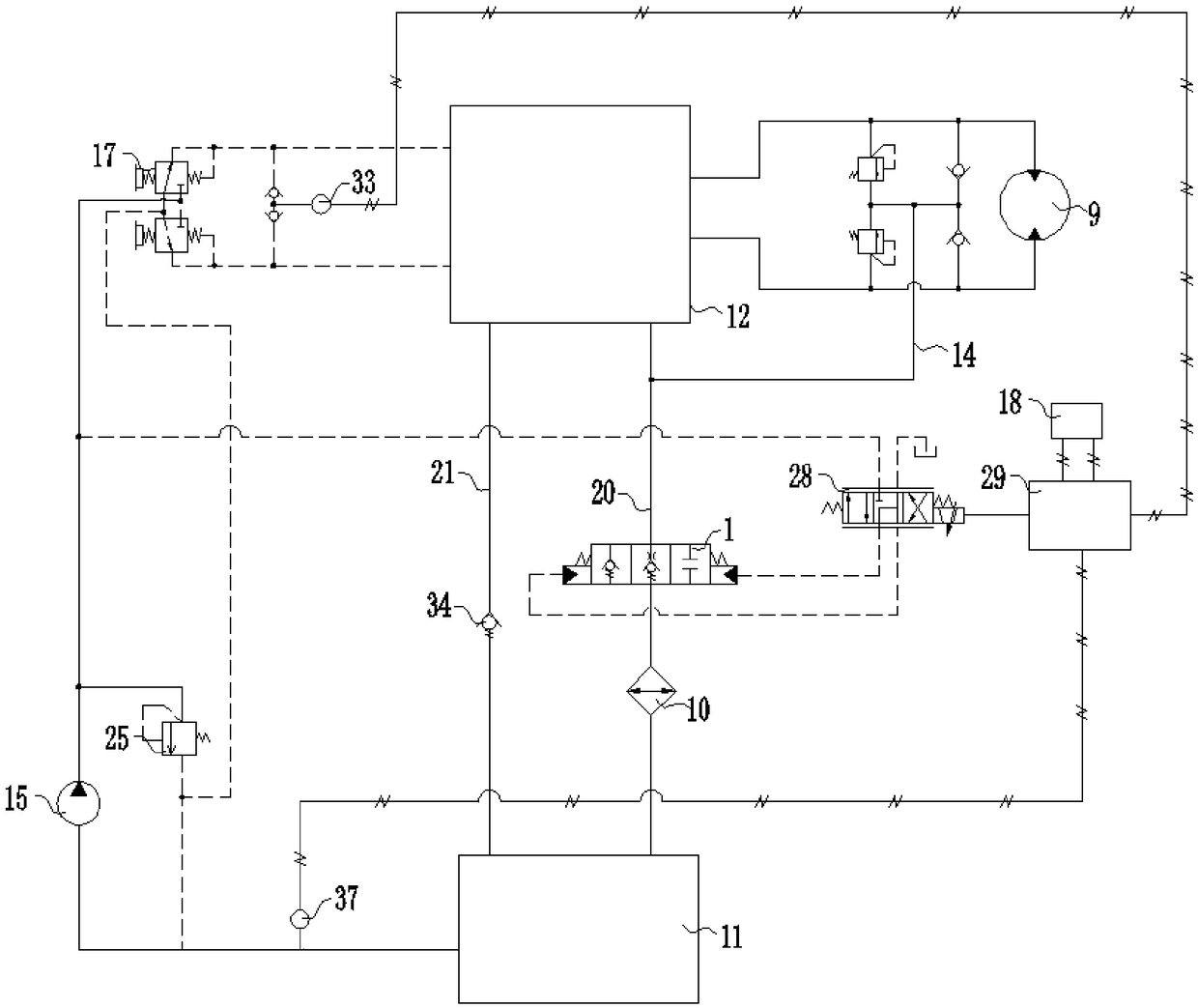
[0023] Such as figure 1 As shown, the hydraulic multi-way valve group 12 is used to control the oil in and out of the entire hydraulic system. The main oil circuit of the multi-way valve group 12 returning oil to the hydraulic oil tank 11 has a first oil return line 20 and a second oil return line 21. The oil return control valve 1 and the radiator 10 are installed on the first oil return circuit 20. The oil return control valve 1 is a three-position two-way hydraulic control valve. The function of the right position realizes conduction but has a certain oil return resistance or the pressure range is between 1bar-4bar, especially 2.5bar. The function of the right position is cut-off or the oil return resistance is very high, for example, the oil return resistance is higher than 5bar and lower than 12bar. Especially 10bar. The second oil return circuit 21 is...


PUM


Abstract

The invention provides an engineering machine hydraulic oil return control loop and method. The engineering machine hydraulic oil return control loop comprises a hydraulic oil tank and a hydraulic multi-way valve set. The hydraulic oil tank communicates with the hydraulic multi-way valve set through a first oil return channel and a second oil return channel. The second oil return channel is provided with a back pressure valve. The first oil return channel is provided with an oil return control valve. The control end of the oil return control valve is connected with an electrical control valve. The control end of the electrical control valve is connected with a control mechanism, so that the control mechanism controls the position of the electrical control valve. The control mechanism is electrically connected with a temperature detecting device detecting the temperature of the hydraulic oil tank. The engineering machine hydraulic oil return control loop achieves control over three different pressure values on a main oil return channel of the hydraulic multi-way valve set, meets demands of multiple working conditions, lowers the energy consumption and improves the whole thermal balance state of the hydraulic system.

Description

technical field [0001] The invention designs a construction machinery hydraulic oil return control circuit and a control method thereof. Background technique [0002] In the hydraulic system of construction machinery, especially in hydraulic excavators, in order to prevent the suction of the rotary motor of the hydraulic actuator, it is necessary to add the first back pressure valve on the oil return line of the hydraulic system, so as to effectively protect the rotary motor, but due to If the pressure of the first back pressure valve is too high, the back pressure of the whole system will be too high, so the second back pressure valve is added to solve the problem that the back pressure value exceeds the hydraulic system’s tolerance when the return oil volume is large, and The setting value of the back pressure valve is generally above 2.5bar. In actual work, the average working pressure reaches above 4.0bar, and the peak value reaches about 7.0bar. This leads to an increas...

Claims


Application Information

Patent Timeline
Patent Type & Authority Patents(China)
IPC IPC(8): F15B13/02
CPCF15B13/02F15B2211/515
Inventor 茅永林陈艳军张新海
Owner 内蒙古山河巨鼎矿用机械制造有限责任公司
Learn More