
Convenient-opening freezer

A technology that is convenient to open and freezer, applied to household refrigerators, coolers, lighting and heating equipment, etc., can solve the problems of high cost, troublesome operation, and effort, and achieve the effect of safe working environment and convenient opening

Active Publication Date: 2018-11-27
浙江欧恒制冷设备有限公司
View PDF8 Cites 1 Cited by
  • Summary
  • Abstract
  • Description
  • Claims
  • Application Information

AI Technical Summary

Problems solved by technology

[0003] Since the inside of the freezer is cooled and stored through the cooling of the gas, when the gas is cooled, the volume of the gas inside the cabinet shrinks, and a negative pressure is formed inside the cabinet, which attracts the cabinet door to move down so that the cabinet door and the cabinet body are close to each other. Tight, it takes a lot of effort to pull up the cabinet door when opening, the operation is very troublesome and laborious

Method used

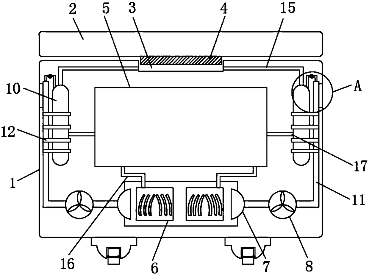

Image

  • Convenient-opening freezer
  • Convenient-opening freezer
  • Convenient-opening freezer

Examples


Embodiment 1

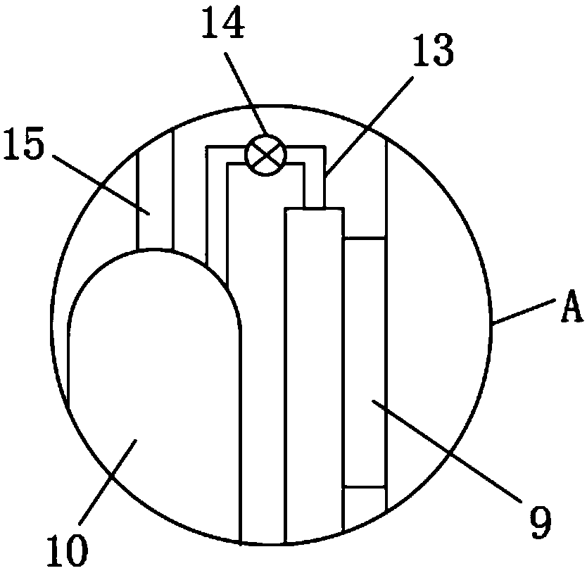
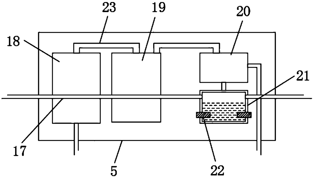
[0025] refer to Figure 1-3 , a freezer that is convenient to open, including a cabinet body 1 and a cabinet door 2 connected by hinge rotation, the upper side wall of the cabinet body 1 is provided with a card slot 3, and the lower side wall of the cabinet door 2 is provided with a card slot 3. Clamps 4 with matching sizes and positions. A cavity is provided inside the cabinet body 1. An electrolysis device is provided in the cavity. The electrolysis device includes a mounting plate 5 and a compressor 18 installed in the mounting plate 5, a refrigerant tank 19, The gas-liquid separator and the electrolytic cell 21, the electrolytic cell 21 communicates with the interior of the two airbags 10 through two connecting pipes 17, the compressor 18 and the refrigerant tank 19 and the refrigerant tank 19 and the gas-liquid separator 20 are all connected through the return pipe 23 Connected, the gas-liquid separator 20 communicates with the inside of the electrolytic tank 21 through t...

Embodiment 2

[0029] refer to Figure 4 , the upper side wall of each airbag 10 is connected with an air delivery pipe 15, the lower side wall of the slot 3 is connected with a plurality of air outlet pipes 24, and the ends of the two air delivery pipes 15 away from the airbag 10 are connected with a plurality of air outlet pipes 24, An air outlet valve 25 is installed on each air delivery pipe 15 .

[0030] for Figure 4 The difference between the illustrated embodiment two and the first embodiment is that the air delivery pipe 15 is directly connected to the side wall of the card slot 3 instead of connecting the air delivery pipe 15 with a plurality of air outlet pipes 24, and the air outlet pipe 24 is connected to the card slot. The inner bottom wall of the groove 3 is connected. Compared with the first embodiment, the gas derived from the lower part is better than the gas blown out from the side wall to lift the clamping plate 3 better, and an air valve 25 is provided to open the cabin...


PUM


Abstract

The invention discloses a freezer which is convenient to open, Cabinet body and cabinet body are connecte with cabinet door through hinge rotation, An upper side wall of that cabinet body is provide with a clamping groove, the lower side wall of the cabinet door is provided with a card plate matched with the size and position of the card slot, The inside of the cabinet body is provided with a cavity, the cavity is provided with an electrolytic device, both sides of the electrolytic device are provided with air bags, the bottom of the cabinet body is provided with a heat dissipation device, theheat dissipation device comprises a heat dissipation tube, and the output end of the input end of the heat dissipation tube is connected with a conduit. The invention utilizes water and heat generated by heat dissipation in the cabinet, generates gas by electrolysis of water, expands the gas by heat utilization, and then leads the gas into a clamping groove through an air conveying pipe, therebypreventing negative pressure suction caused by a clamping plate in a low-temperature environment in the cabinet, and ensuring convenient opening of the cabinet door.

Description

technical field [0001] The invention relates to the technical field of freezers, in particular to a freezer that is convenient to open. Background technique [0002] A freezer is a device that cools gas to preserve items, and is widely used in homes or shopping malls. [0003] Since the inside of the freezer is cooled and stored through the cooling of the gas, when the gas is cooled, the volume of the gas inside the cabinet shrinks, and a negative pressure is formed inside the cabinet, which attracts the cabinet door to move down so that the cabinet door and the cabinet body are close to each other. Tight, it takes a lot of effort to pull up the cabinet door when it is opened, and the operation is very troublesome and laborious. [0004] For this reason, we have proposed a kind of freezer that is convenient to open to solve the above problems. Contents of the invention [0005] The purpose of the present invention is to solve the problems in the background technology, an...

Claims


Application Information

Patent Timeline
IPC IPC(8): F25D11/00F25D23/02F25D17/04
CPCF25D11/00F25D17/047F25D23/028F25D2317/04F25D2323/02
Inventor 杨浩
Owner 浙江欧恒制冷设备有限公司
Learn More